Standards & methods reference
NABL accredited testing laboratory vide certificate no. TC-12060 (ISO/IEC 17025:2017): three disciplines — Electronics, Mechanical, Fluid flow — nine accredited groups, six labs on one campus in Hyderabad. The full method tables for each lab, for engineers preparing a test request. For the plain-language view start at Testing. Standards listed are those we run routinely. Only the methods in the scope of accreditation are accredited; other tests are offered as non-accredited services and reported without the NABL symbol. Ranges are published capability limits — for a specific profile, send it and we'll verify it against the machine.
Dynamic test lab
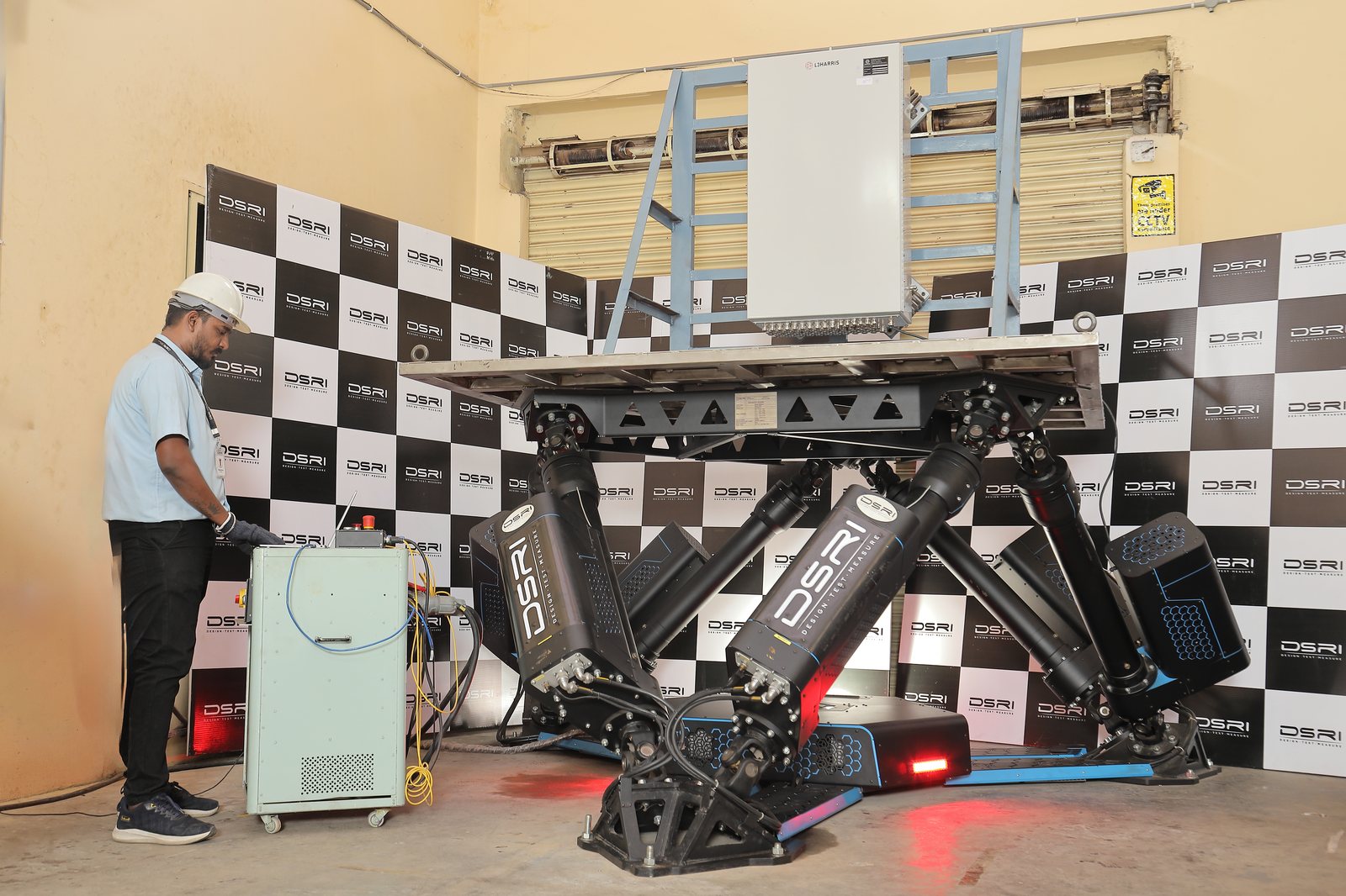
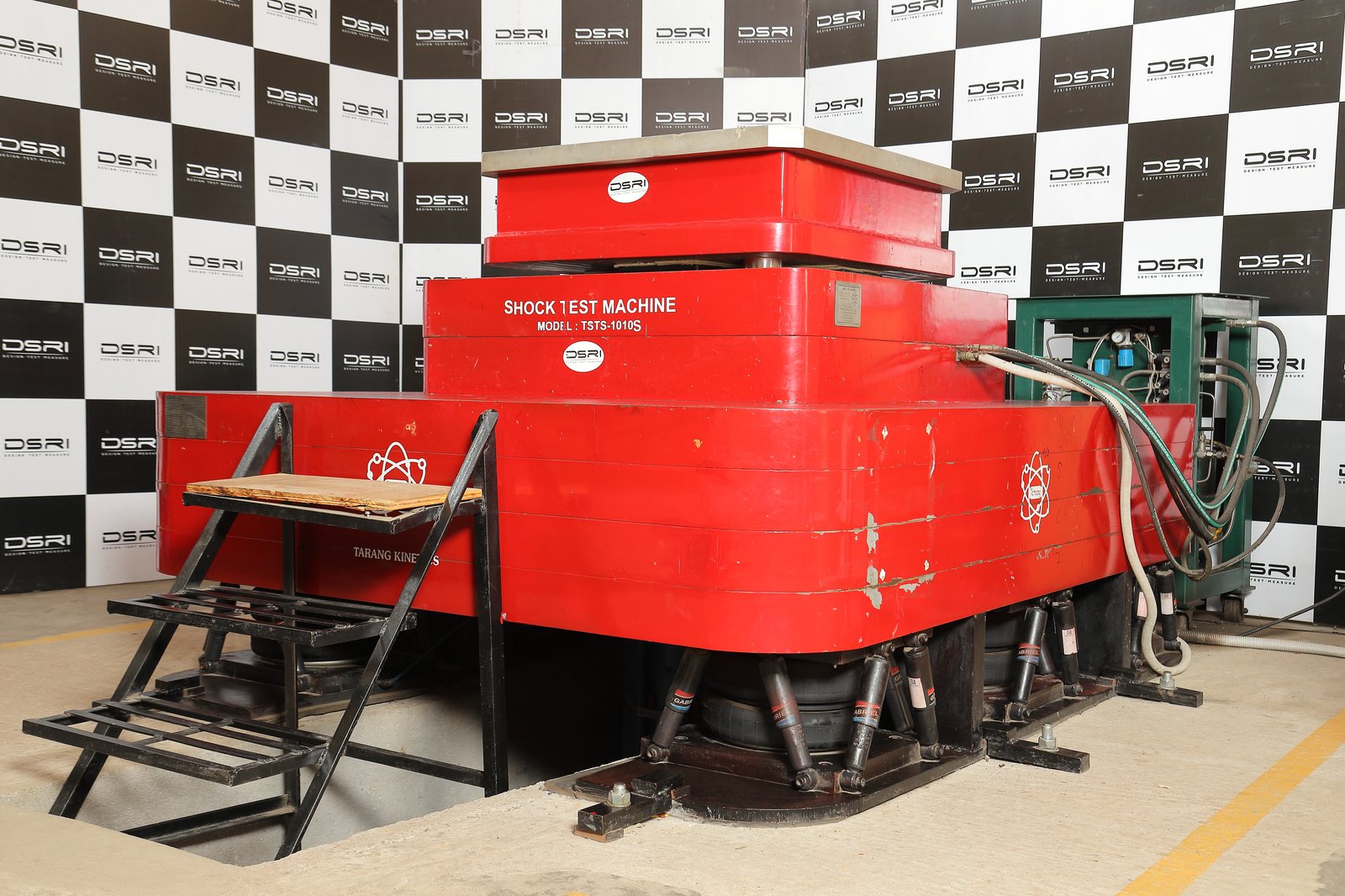
Electrodynamic shakers from bench-top to 16,000 kgf, classical shock and bump machines, a centrifuge for steady-state acceleration and a six-axis ship-motion simulator. Test profiles are verified against machine capability before quotation.
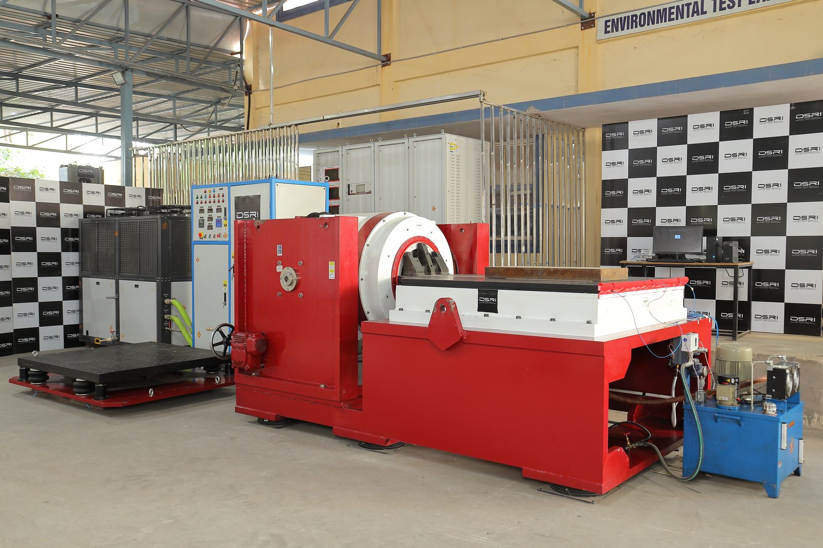
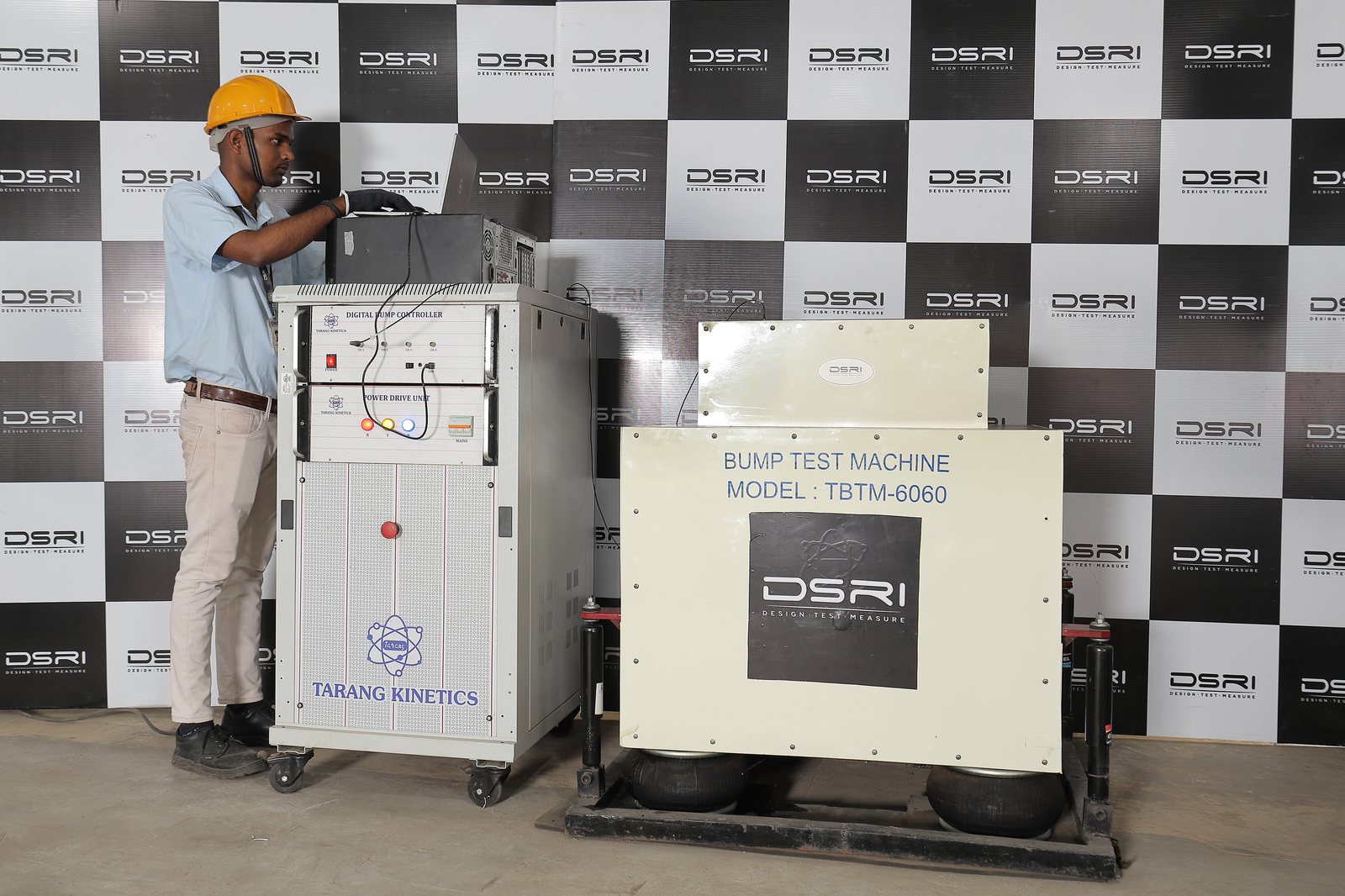
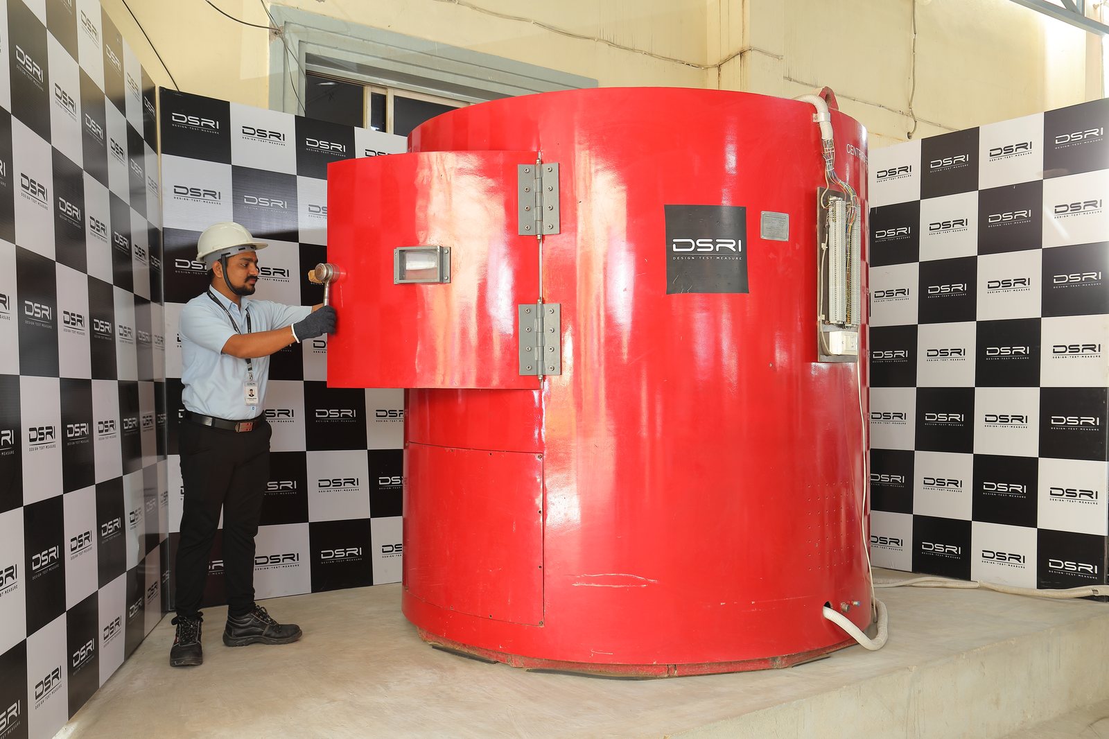
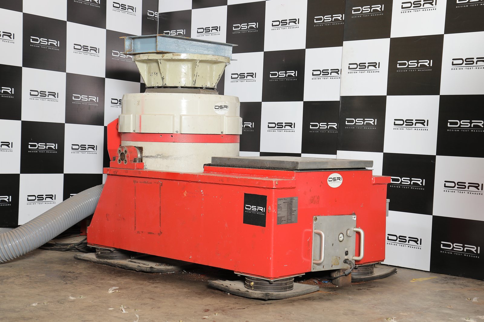
The methods below are in the NABL scope of accreditation (TC-12060) and are reported under the NABL symbol. Sine vibration is accredited from 5 Hz to 2,000 Hz and 0.1 g to 30 g at up to 16,000 kgf; other profiles, levels or customer specifications are reported as non-accredited. Plain-language version: Dynamic test lab.
Vibration
sine · random · rail · shipboardSine vibration & resonance search
Swept or fixed-frequency sinusoidal excitation on the vertical head or horizontal slip table, with a resonance search before and after endurance and dwells at the resonances found. Time-history and sine-beat methods for equipment that must survive short, strong transients.
We report- Control and response plots for every axis
- Resonance frequencies before and after endurance
- Visual inspection and observations
Random vibration
Broadband random vibration under closed-loop digital control to a specified acceleration spectral density, per axis, for the specified duration — the closest laboratory match to road, air and sea transport.
We report- ASD control plots against the tolerance bands
- Overall g RMS and duration per axis
- Visual inspection and observations
Railway rolling-stock equipment
Functional random vibration, simulated long-life testing at increased random levels (0.5 g to 75 g) and shock, by category and mounting location on the vehicle.
We report- Functional and long-life ASD plots
- Shock pulses per direction
- Visual inspection and observations
Shipboard vibration
Environmental (Type I) vibration of shipboard equipment — exploratory, variable-frequency and endurance at the resonances found — and internally excited (Type II) vibration of machinery.
We report- Exploratory and endurance records
- Resonances and dwell durations
- Visual inspection and observations
Shock, bump & drop
half-sine · repeated shock · handlingClassical shock
Half-sine (and, by programme, saw-tooth and trapezoidal) shock pulses of specified peak acceleration and duration, in each direction of each axis — up to 30,000 g on the shock machine.
We report- Recorded pulse against the tolerance band
- Peak g, duration and number of shocks per direction
- Visual inspection and observations
Bump (repeated shock)
Thousands of repeated half-sine pulses at 3 g to 60 g on the big and small bump machines — the fatigue loading of rough roads and handling.
We report- Peak g, pulse duration and number of bumps
- Pulse record
- Visual inspection and observations
Drop, topple & rough handling
Free fall and repeated free fall, drop and topple, and transit drops in packed condition — onto faces, edges and corners from specified heights.
We report- Drop heights and orientations
- Number of drops
- Visual inspection and observations
Acceleration & motion
centrifuge · tilt · six-axis motionSteady-state acceleration
Sustained acceleration of 1 g to 100 g on the centrifuge, in each specified direction, for the specified duration — the loads of manoeuvring aircraft, missiles and launch.
We report- g level, duration and direction
- Visual inspection and observations
Ship-motion simulation
Roll, pitch, yaw, heave, surge and sway on the six-axis ship-motion simulator, at specified amplitudes and periods — the only such machine in India's private sector.
We report- Motion amplitudes, periods and duration
- Visual inspection and observations
Tilt & inclination
Static and dynamic inclination from 0° to 45° in each specified direction, for shipboard and offshore equipment.
We report- Angles, directions and durations
- Visual inspection and observations
| Test | Range · methods (accredited methods: see scope) |
|---|---|
| Sine, random & sine-on-random vibration | JSS 55555 (Test 28) · MIL-STD-810 F/G/H Method 514 · JSS 0256-01 (Test 15) · IEC 60068-2-6/-64 · IEC 61373 · IS 9000 · MIL-STD-167-1A · IEC 60517 |
| Classical shock | up to 30,000 g · JSS 55555 (Test 24) · MIL-STD-810 Method 516 · JSS 0256-01 (Test 18) · IEC 60068-2-27 · IS 9000 (Part 7) · ISO 16750-4 · JSS 50101 · IN Shock Grade A · NSS I / NSS II |
| Bump (half sine) | 3 g – 60 g · JSS 55555 (Test 5) · IS 10236 (Part 10) · IEC 60255-21-2 · IEC 60571 · JSS 0256-01 (Test 23) |
| Acceleration (steady state) | 1 g – 100 g · JSS 55555 (Test 1) · MIL-STD-810 Method 513 · JSG 0102 (Test 22) · JSS 0256-01 (Test 16) |
| Tilt / inclination | 0° – 45° · JSS 55555 · naval specifications |
| Ship-motion simulation | roll, pitch, yaw, heave, surge, sway · naval and marine equipment qualification |
Equipment
- 16,000 kgf & 4,000 kgf electrodynamic shakers with slip tables
- LDS shaker
- Shock test machine
- Big & small bump machines
- Ship-motion machine
Climatic test lab
Walk-in chambers (2 m and 5 m) and bench chambers cover −70 °C to +180 °C with humidity to 98 % RH and thermal cycling at 15 °C/min, plus dedicated salt-corrosion, mould-growth, dust, water, drip and driving-rain facilities.
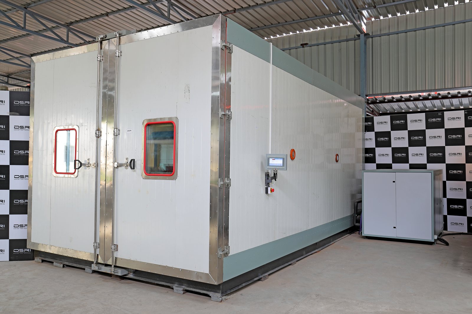
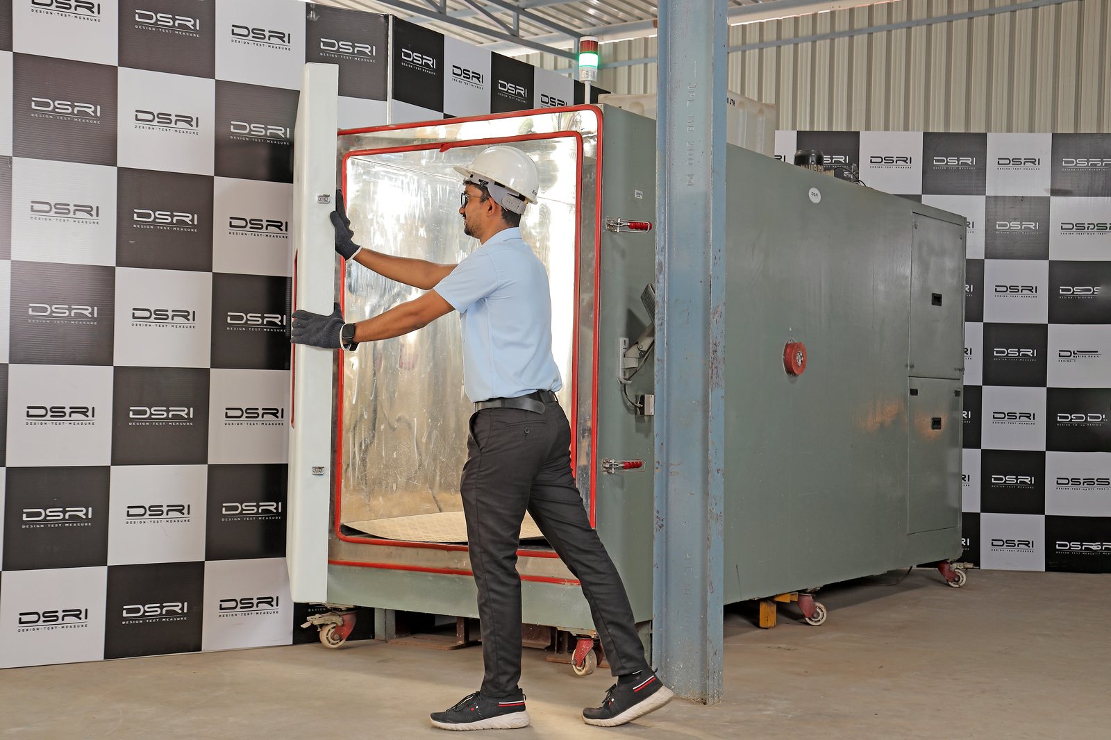
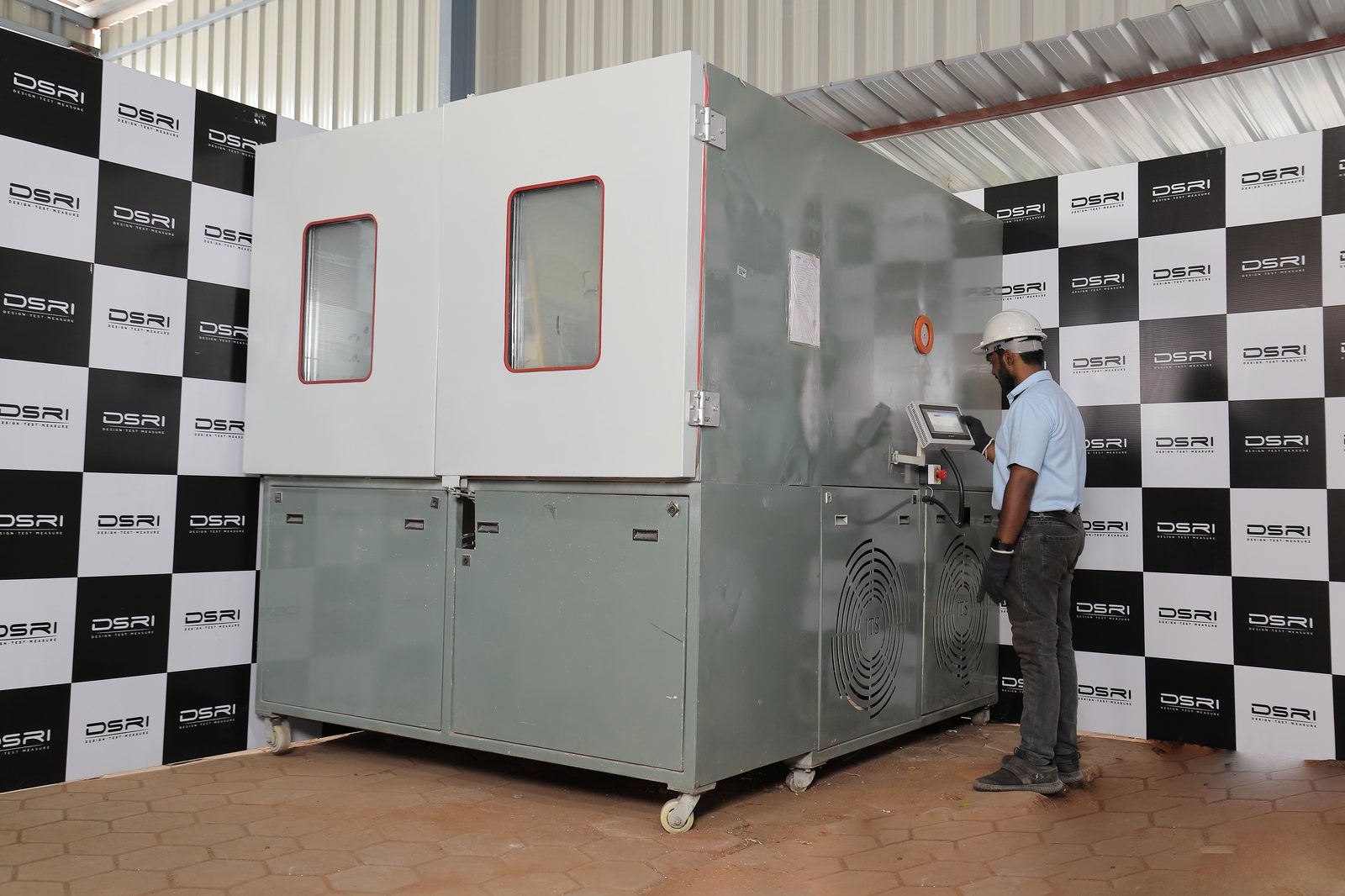
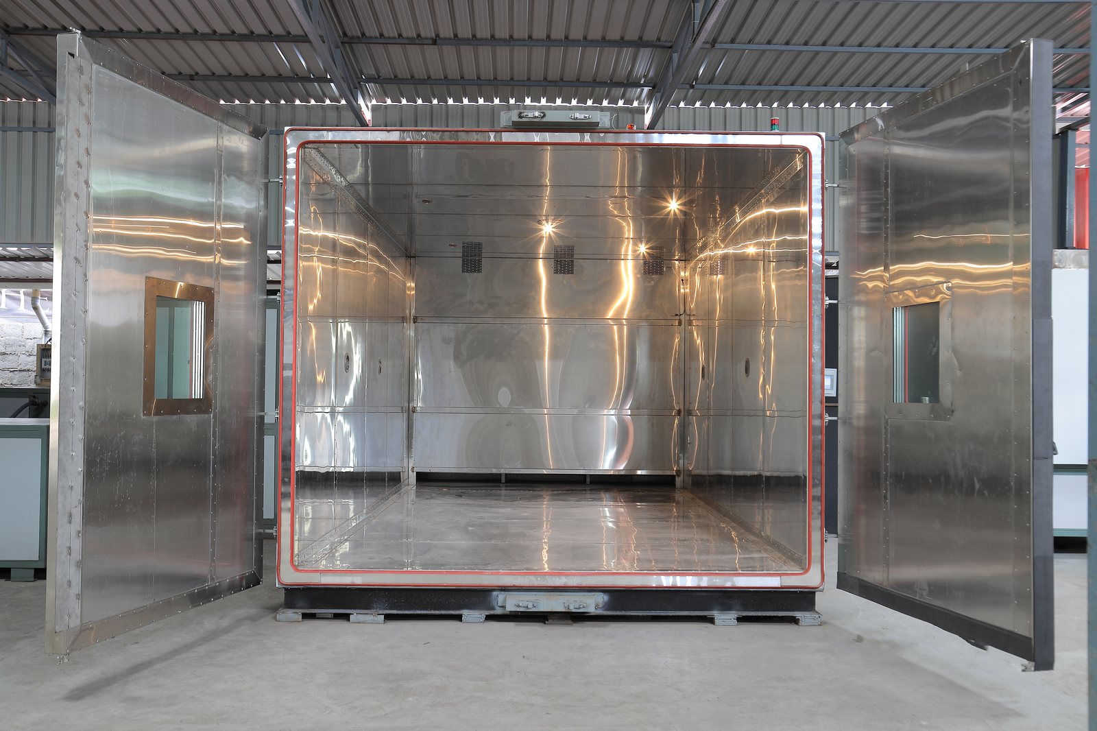
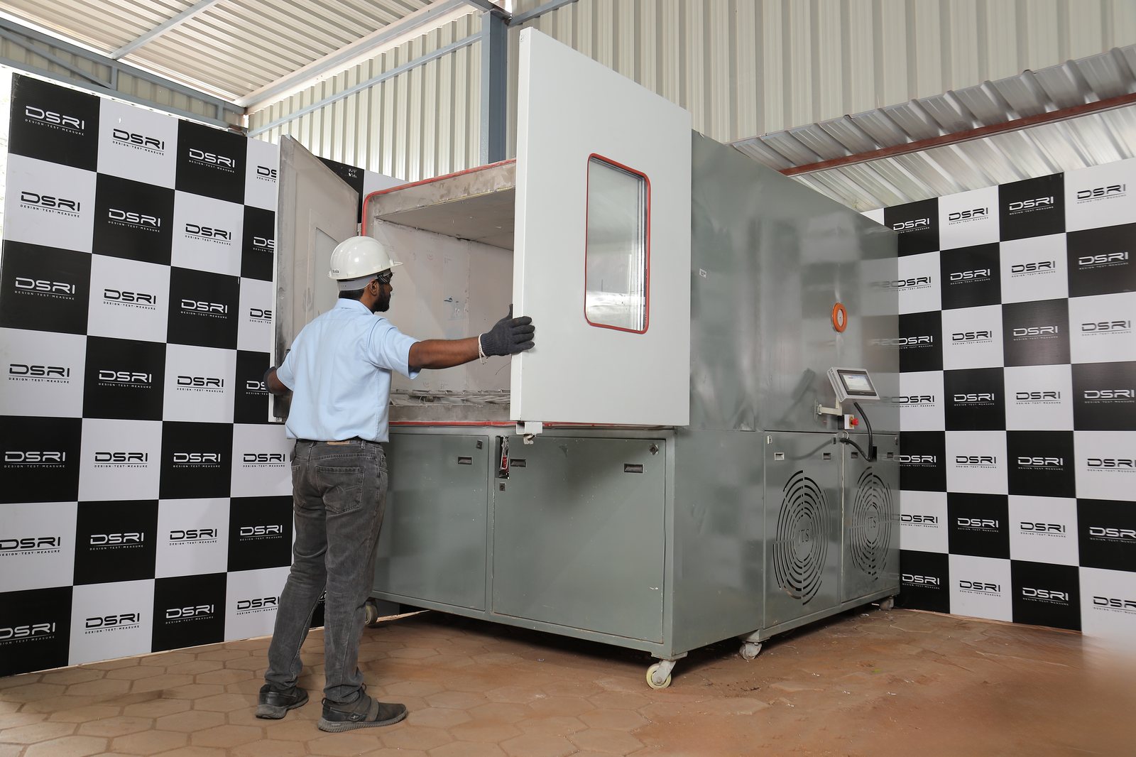
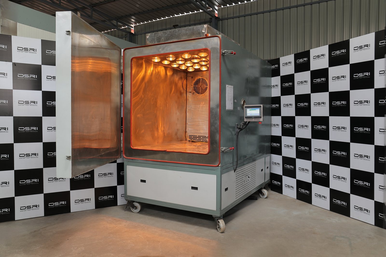
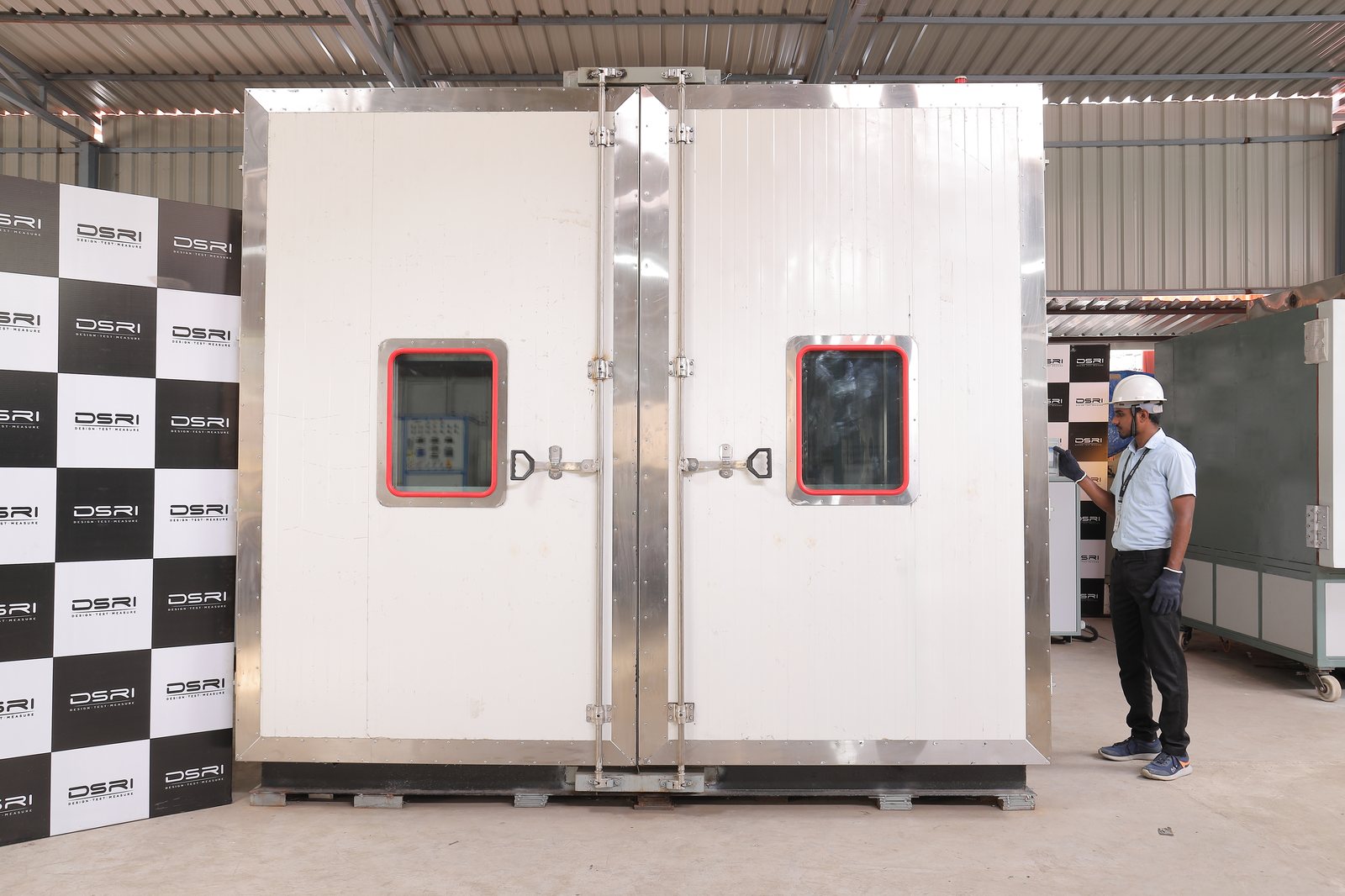
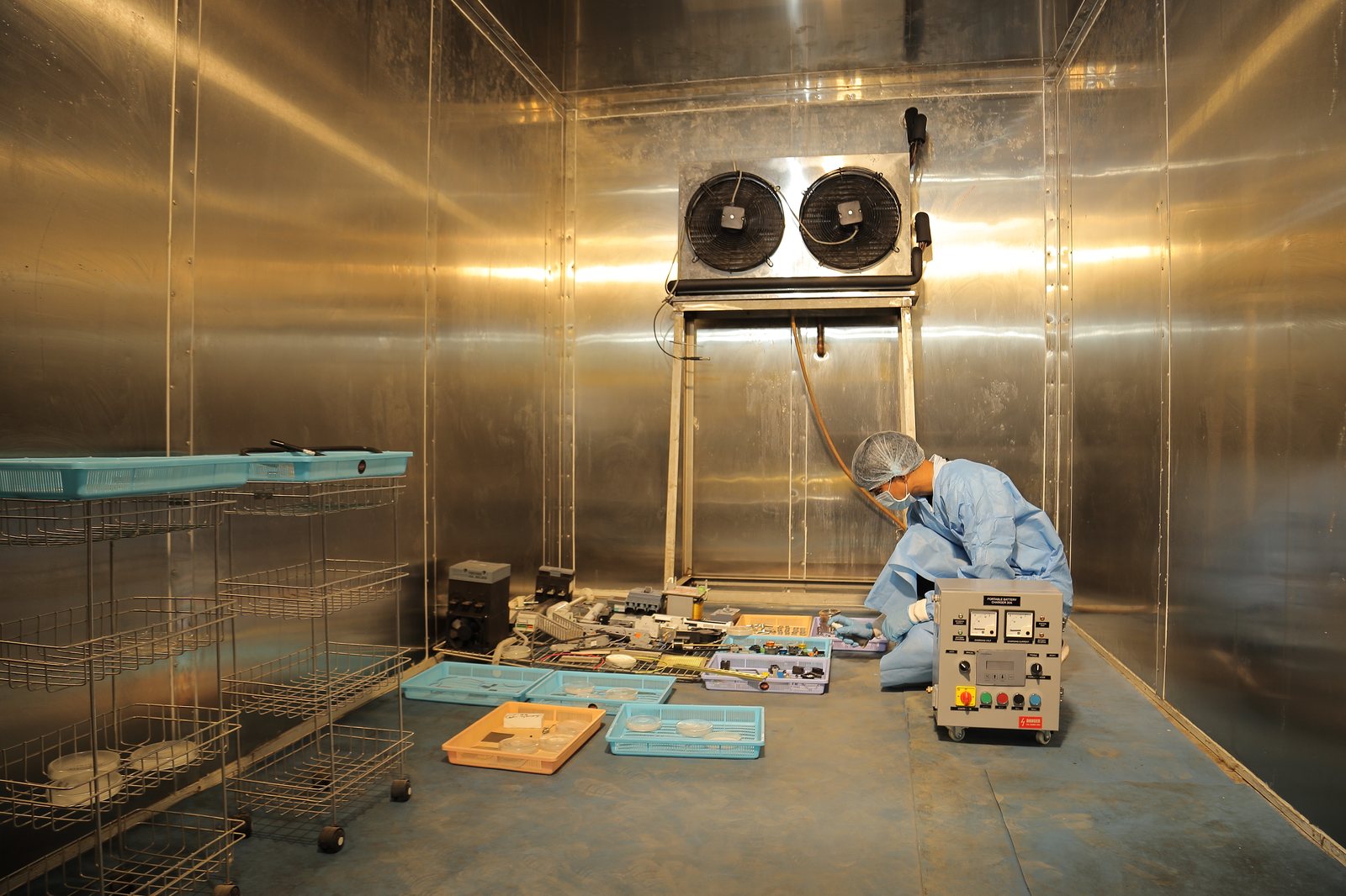
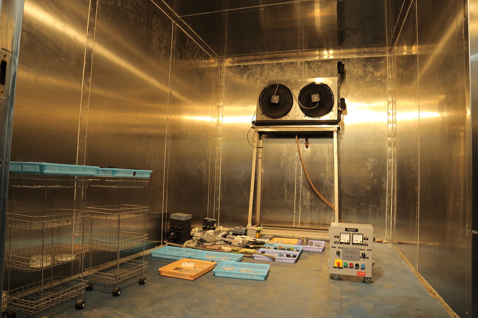
The methods below are in the NABL scope of accreditation (TC-12060) and are reported under the NABL symbol. Chamber sizes and ranges are published capability; other profiles or customer specifications are reported as non-accredited. Plain-language version: Climatic test lab.
Temperature
dry heat · cold · change of temperature · ESSHigh temperature (dry heat)
Storage and operating exposure at up to +180 °C for the specified duration, with the unit switched on where the standard requires, and recovery before final inspection.
We report- Chamber temperature record for the whole exposure
- Exposure durations, operating and storage
- Inspection and observations before and after
Low temperature (cold)
Storage and operating exposure down to −70 °C, including cold start, with controlled recovery to avoid condensation damage.
We report- Chamber temperature record
- Exposure durations, operating and storage
- Inspection and observations before and after
Change of temperature & thermal shock
Cycling between hot and cold extremes at up to 15 °C/min in one chamber, or rapid transfer between two for thermal shock, for the specified number of cycles.
We report- Temperature–time record of every cycle
- Number of cycles, dwell times and transition rates
- Inspection and observations
Environmental stress screening (ESS)
Production screening with thermal cycling (and vibration where specified) to precipitate latent manufacturing defects before delivery.
We report- Screening profile record per unit
- Failures found during screening
- Observations
Humidity & tropical
damp heat · tropical exposure · mould growthDamp heat (steady & cyclic)
Steady-state or cyclic humidity at up to 98 % RH, including composite temperature–humidity cycling, in chambers up to 2.1 × 1.0 × 1.4 m.
We report- Temperature and humidity record for the whole test
- Number of cycles or days
- Inspection and observations
Tropical exposure
Long-duration exposure in the 3 × 3 × 5 m walk-in room at 20 °C to 75 °C and 30 % to 95 % RH, for large equipment and complete assemblies.
We report- Temperature and humidity record
- Exposure duration
- Inspection and observations
Mould growth (fungus)
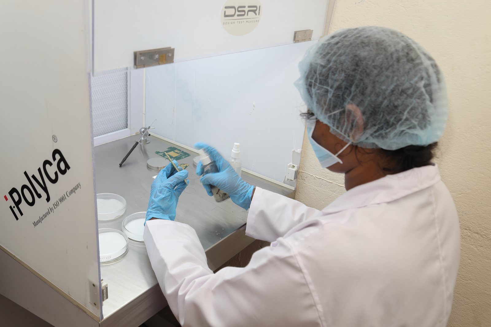
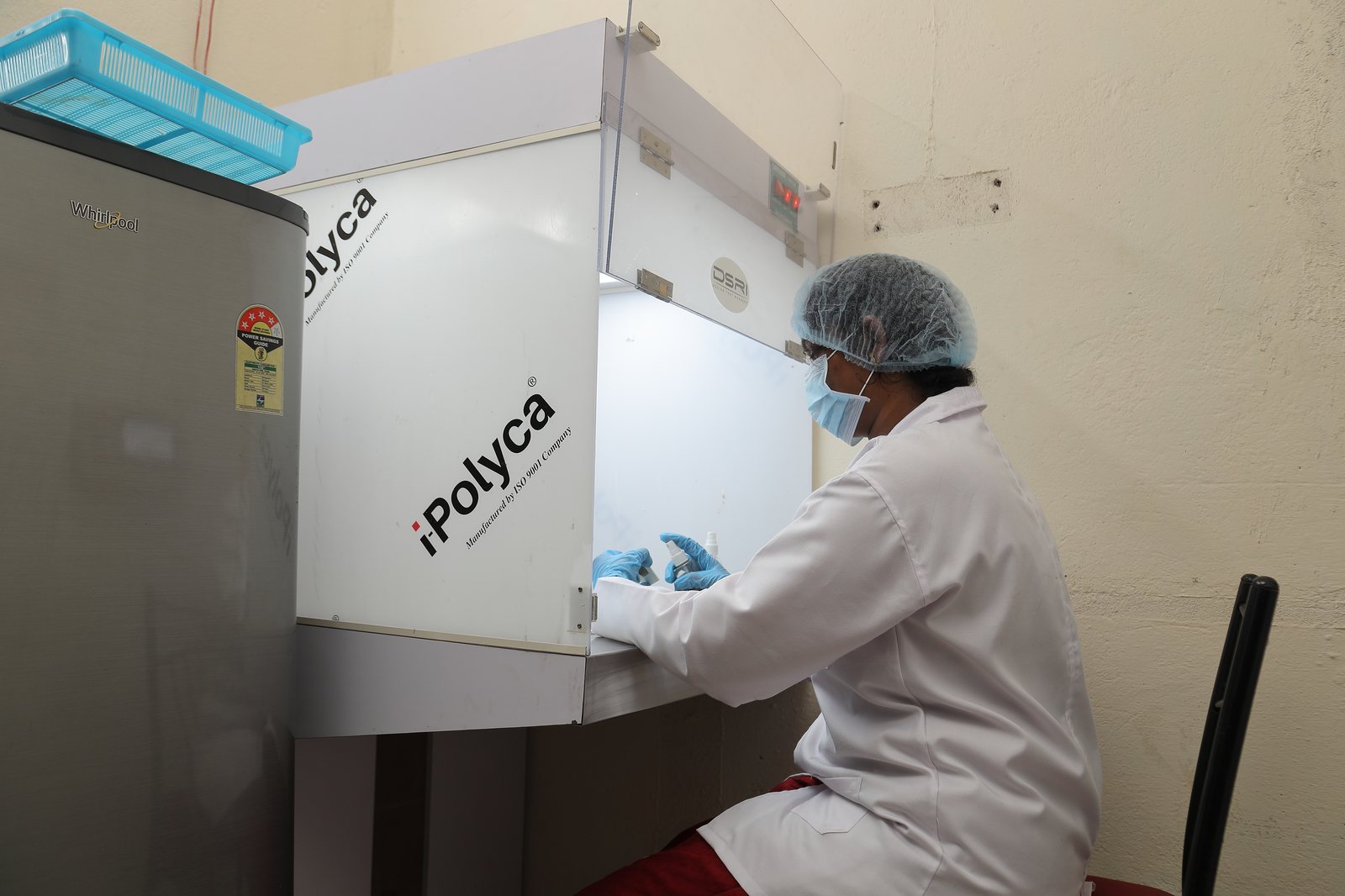
Inoculation with specified fungal spores and incubation in warm, humid conditions for the specified period, then assessment of growth.
We report- Growth rating for each surface assessed
- Incubation conditions and duration
Corrosion, solar & altitude
salt fog · solar radiation · low pressureSalt fog / salt mist
Continuous or cyclic exposure to neutral salt fog for the specified duration, followed by inspection for corrosion and loss of function.
We report- Salt-fog conditions and duration
- Corrosion observed on each surface
- Inspection and observations
Solar radiation
Simulated sunlight at ground level for heating effects and for photodegradation of materials, by cycle or steady state.
We report- Irradiance and temperature record
- Exposure duration or cycles
- Inspection and observations
Altitude / low pressure
Low air pressure alone or combined with temperature and humidity in the 2.5 × 2.5 × 4 m CATH chamber, at −30 °C to +150 °C.
We report- Pressure, temperature and humidity record
- Exposure duration
- Inspection and observations
Dust, water & fluids
IP codes · rain · immersion · contaminationDust & sand
Fine dust (IP 5X / 6X) and blowing sand and dust, with inspection of the enclosure interior for ingress.
We report- IP rating tested and result
- Exposure conditions and duration
- Interior inspection observations
Water: drip, rain, jets & immersion
Drip, spray, driving rain, water jets and temporary or continuous immersion — IP X1 to X8 — with interior inspection after each.
We report- IP rating tested and result
- Water conditions and duration
- Interior inspection observations
Contamination by fluids
Exposure to fuels, oils, hydraulic fluids, cleaning agents and other specified fluids, then inspection for swelling, cracking and loss of function.
We report- Fluids, exposure method and duration
- Inspection and observations
| Test | Range · methods (accredited methods: see scope) |
|---|---|
| High temperature | up to +180 °C · JSS 55555 (Test 17) · MIL-STD-810 Method 501 · IEC 60068-2-2 · IS 9000 (Part 3) · IEC 60571 · QM 333 |
| Low temperature | down to −70 °C · JSS 55555 (Test 20) · MIL-STD-810 Method 502 · IEC 60068-2-1 · IS 9000 (Part 2) · JSS 0256-01 (Test 2) |
| Damp heat (steady & cyclic) / humidity | up to 98 % RH · JSS 55555 (Test 10) · MIL-STD-810 Method 507 · IEC 60068-2-30/-38/-78 · IS 9000 (Parts 4, 5, 6) · IEC 60945 |
| Thermal cycling / change of temperature / thermal shock | 15 °C/min · JSS 55555 (Test 22) · MIL-STD-810 Method 503 · IEC 60068-2-14 · IS 9000 (Part 14) · JSS 0256-01 (Test 5) |
| Salt spray / salt fog / corrosion | JSS 55555 (Test 9) · MIL-STD-810 Method 509 · ASTM B117 · JSS 0256-01 (Test 12) · IEC 60495 · ISO 16750-4 |
| Dust & sand | IP 5X / IP 6X · IEC/IS 60529 · JSS 55555 (Test 12) · MIL-STD-810 Method 510 |
| Water: drip, driving rain, immersion | IP X1 – X8 · IEC 60529 · JSS 55555 (Tests 11, 14) · IS 9000 (Part 16) · MIL-STD-810 Method 506 |
| Mould growth / fungus | JSS 55555 (Test 21) · MIL-STD-810 Method 508 · IS 9000 (Part 10) · JSS 0256-01 (Test 13) |
| Tropical exposure, altitude, contamination by fluids | JSS 55555 · MIL-STD-810 Methods 500 & 504 · JSS 5855-11 |
Equipment
- 2 m and 5 m walk-in chambers
- Combined altitude-temperature-humidity (CATH) chamber
- Envitronics & Zeta-Tek climatic chambers
- Salt-corrosion chamber
- Mould-growth chamber
- Hot oven
Fluid flow test lab
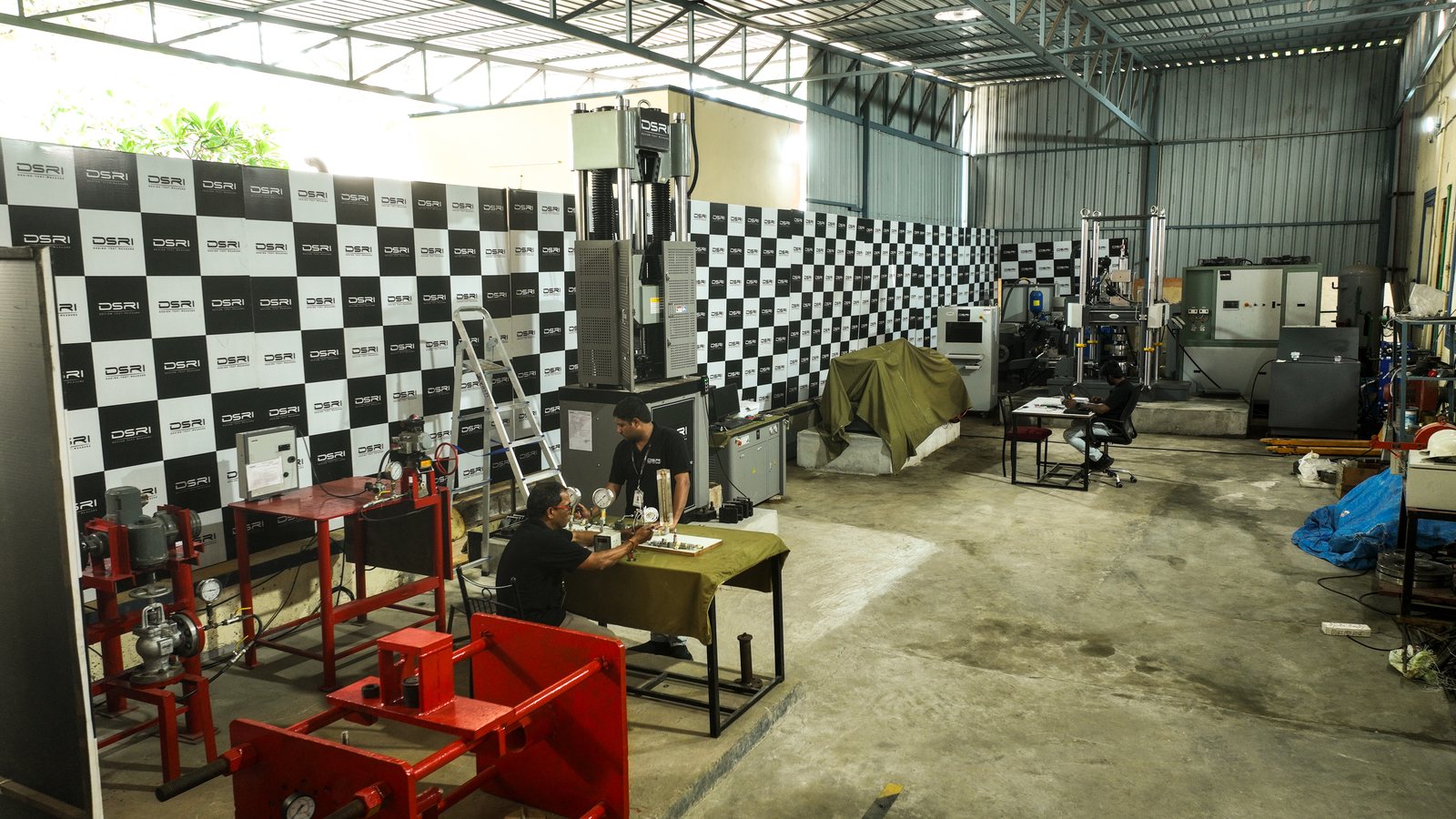
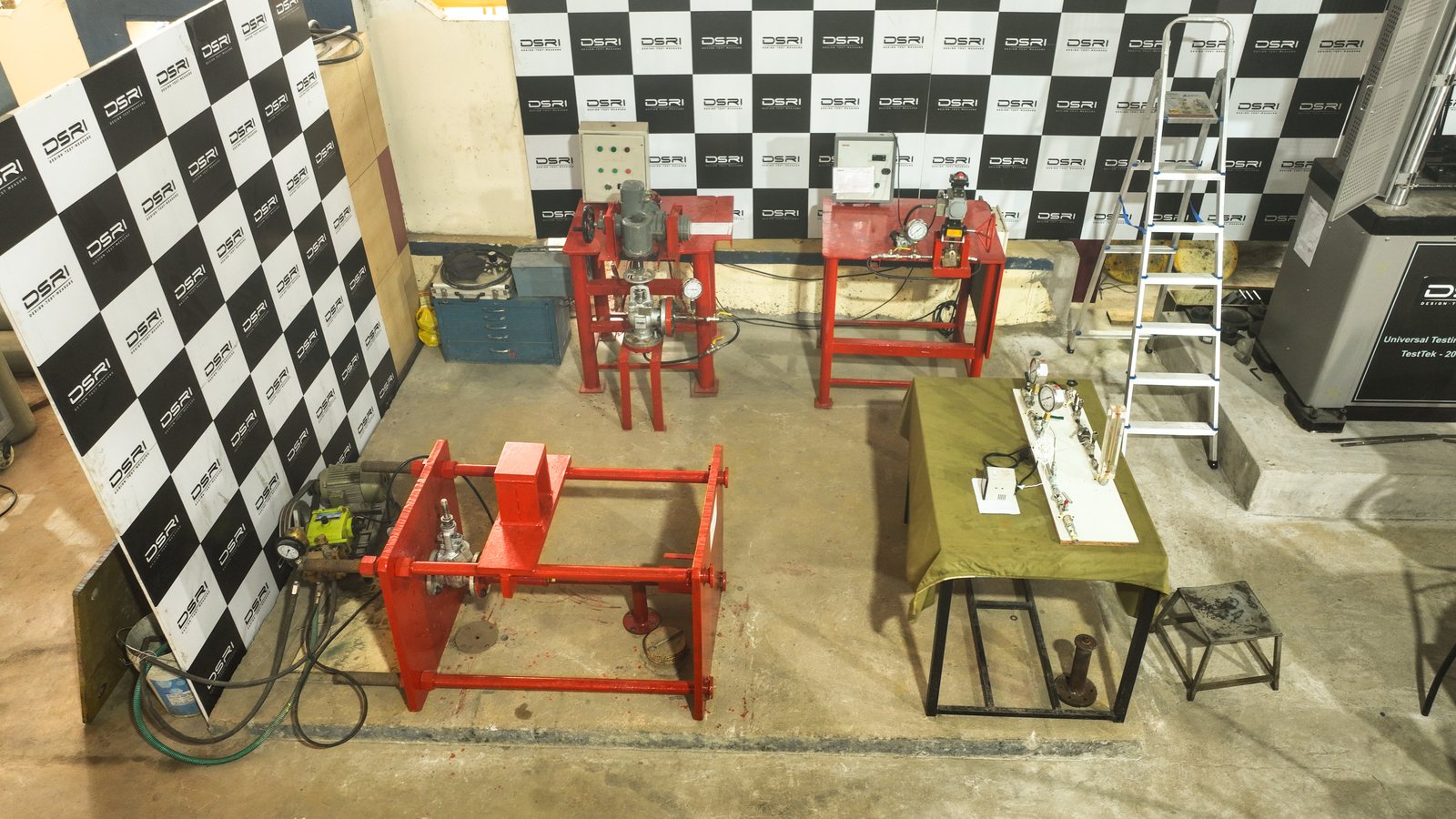
Two accredited groups: liquids (water, oil) and air & gases (air, nitrogen). Proof, burst and life-cycle testing of valves, fittings and hoses, flow-coefficient (Cv) determination and fire-type valve testing to naval and industry standards.
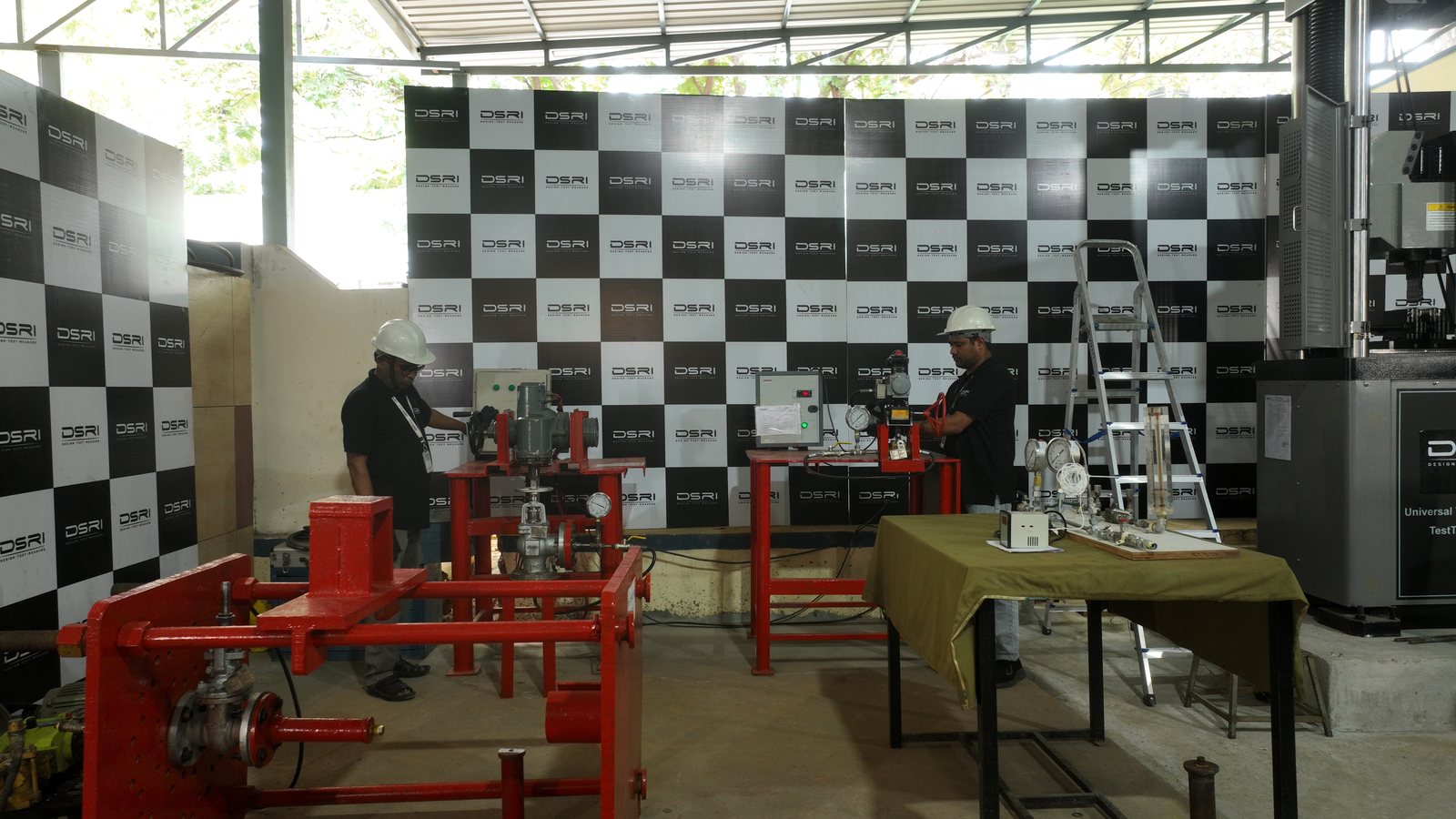
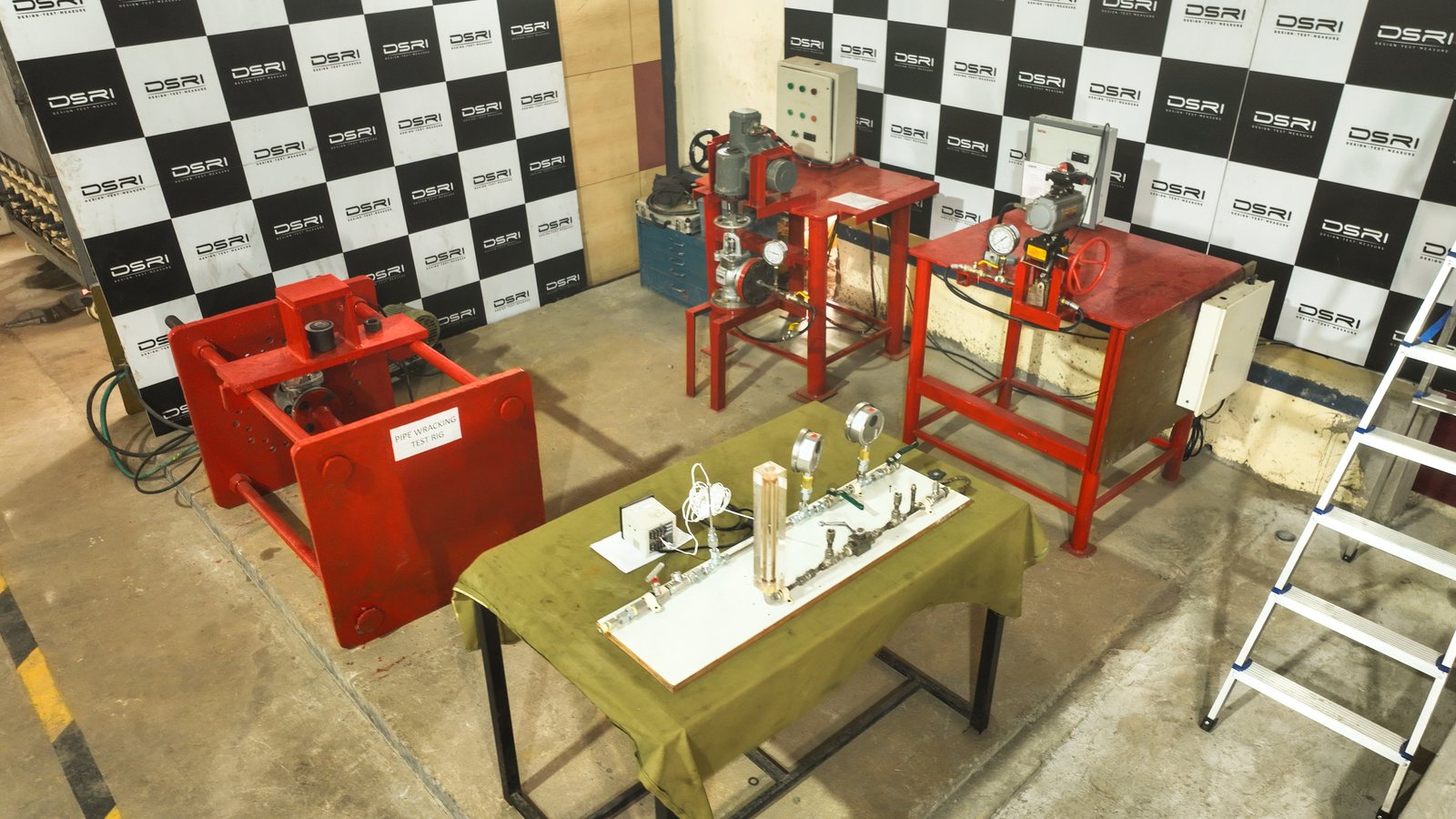
Liquids
Hydraulic proof, seat and shell leak, burst, flow coefficient, life cycle, dismantling & reassembly, pipe wracking, fire-type.
Air & gases
Pneumatic proof and leak on air and nitrogen; low-pressure and vacuum decay by arrangement.
The methods below are in the NABL scope of accreditation (TC-12060) — in the liquids group, the air & gases group, or both — and are reported under the NABL symbol. Other media, pressures or customer specifications are reported as non-accredited. Plain-language version: Fluid flow test lab.
Pressure, leak & burst
hydraulic · pneumatic · burstHydraulic proof, shell & seat tests
Shell strength and seat tightness of valves, and hydraulic proof of pipe and tube fittings, on water or oil at the specified pressure and hold time.
We report- Test pressure, medium and hold time
- Leakage measured or observed against the allowable rate
- Pass / fail against the standard
Pneumatic test
Shell and seat tests of valves and pneumatic tests of fittings on air or nitrogen — more searching for small leak paths than water.
We report- Test pressure, gas and hold time
- Leakage measured or observed
- Pass / fail against the standard
Burst test
Pressure raised on a fitting assembly beyond its rating to the specified burst pressure, or to failure, on liquid or gas.
We report- Pressure reached and hold
- Failure pressure and location, if it failed
Flow & endurance
Cv · life cycleFlow coefficient (Cv / Kv)
Measured flow and pressure drop across the valve at a series of openings on the flow loop, reduced to Cv / Kv and the inherent flow characteristic.
We report- Cv / Kv at each opening
- Flow characteristic curve
- Test conditions
Life cycle
Repeated open–close operation of manual or actuated valves under specified pressure for the specified number of cycles, with seat and shell checks at intervals.
We report- Cycles completed
- Leakage checks at intervals
- Observations
Fittings & fire
reassembly · wracking · fire-typeDismantling & reassembly
Fittings are assembled, pressure tested, taken apart and re-made the specified number of times, then re-tested for leak tightness.
We report- Number of make–break cycles
- Pressure test result after each
- Observations
Pipe wracking
The pressurised fitting assembly is bent back and forth to specified deflections to represent ship-hull movement, then checked for leaks.
We report- Deflections and cycles applied
- Leak check result
Fire-safe (fire-type) testing
Valves exposed to a specified fire while pressurised, then checked for through-seat and external leakage and operability after cool-down — the basis of a valve's fire-safe rating.
We report- Fire and pressure conditions
- Leakage during and after the fire
- Operability after the test
| Test | Range · methods (accredited methods: see scope) |
|---|---|
| Hydraulic proof test — liquids | NES 375 · BS 4368 · ASME F1387 · BS EN 12266-1/-2 |
| Pneumatic test — air & gases | NES 375 · BS 4368 · ASME F1387 · BS EN 12266-1/-2 |
| Burst test — liquids | ASME F1387 · BS 4368 · IS 10103 |
| Flow coefficient (Cv) test | ANSI/ISA-75.01 / 75.02 · NES 375 |
| Life cycle test | NES 375 · DME SPEC 463 · ANSI/AWWA C504 |
| Dismantling & reassembly | ASME F1387 · BS 4368 · IS 10103 |
| Pipe wracking test | NES 375 |
| Fire-type valve testing | BS 6755 Part 2 · ISO 10497 |
Equipment
- Hydraulic and pneumatic test rigs
- Flow-coefficient loop
- Burst and life-cycle stands
Mechanical & materials
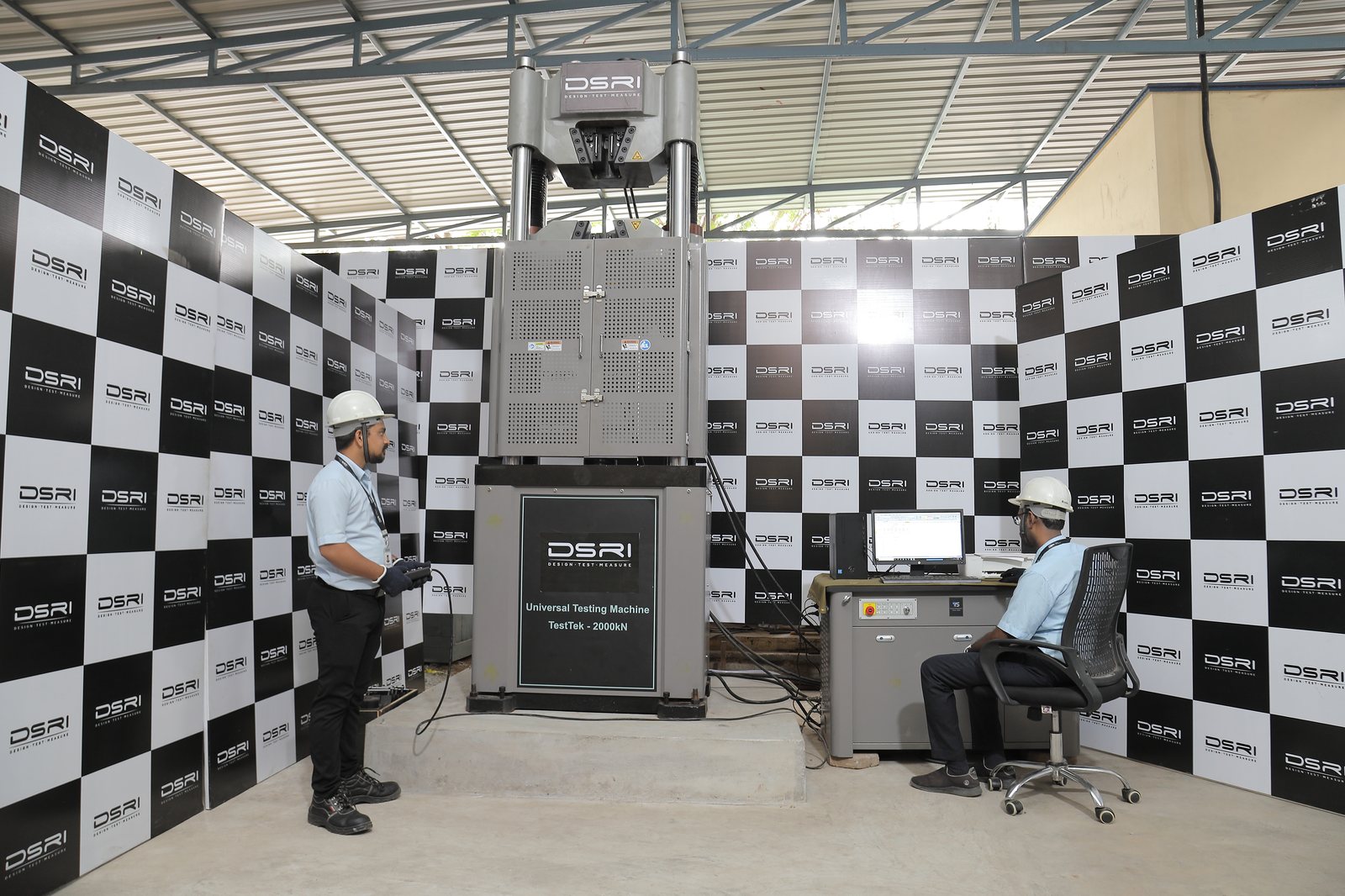
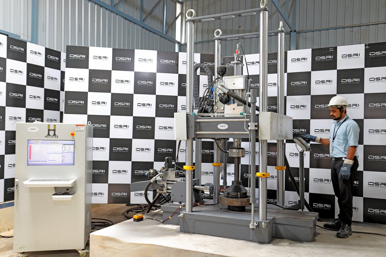
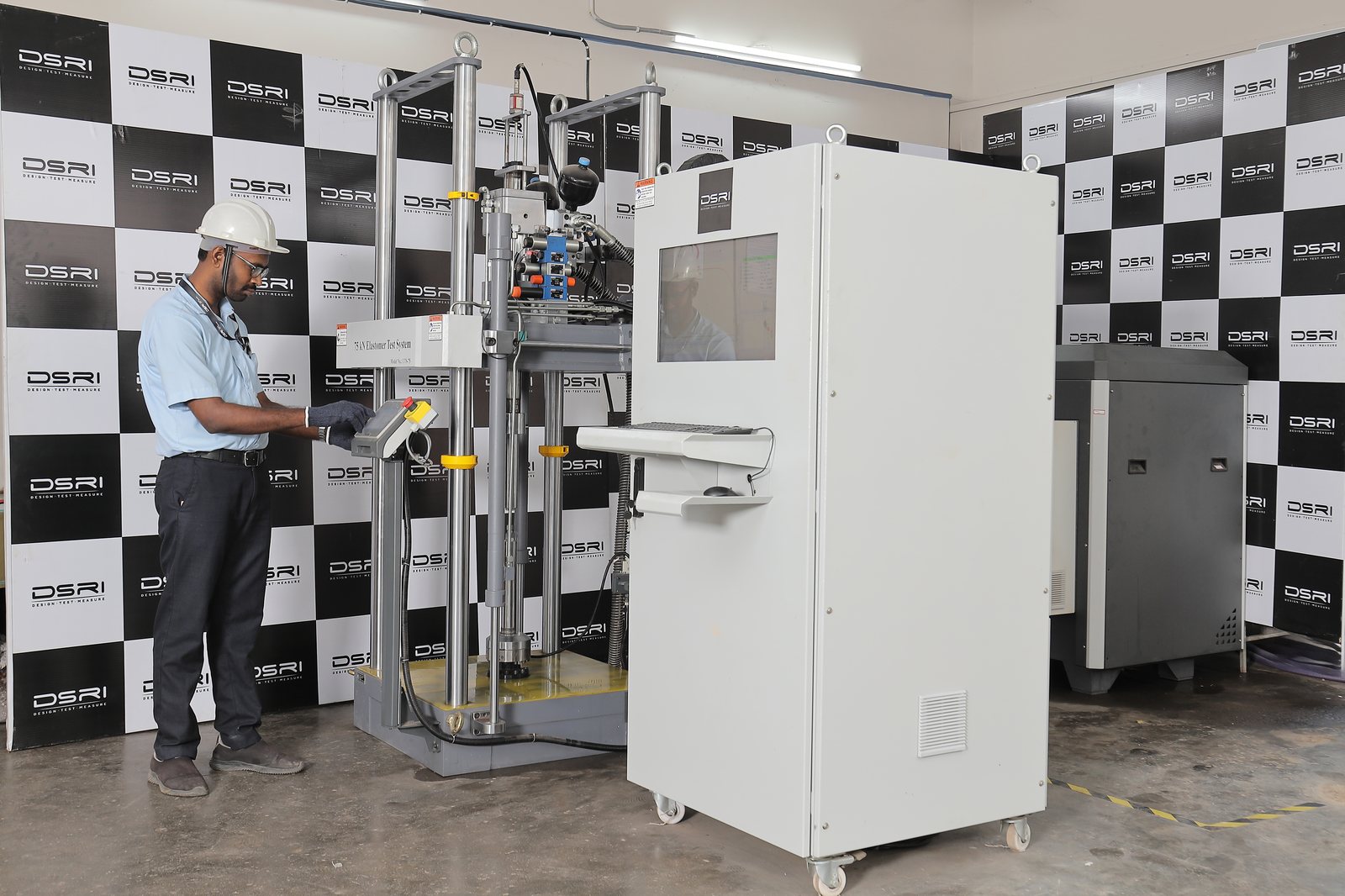
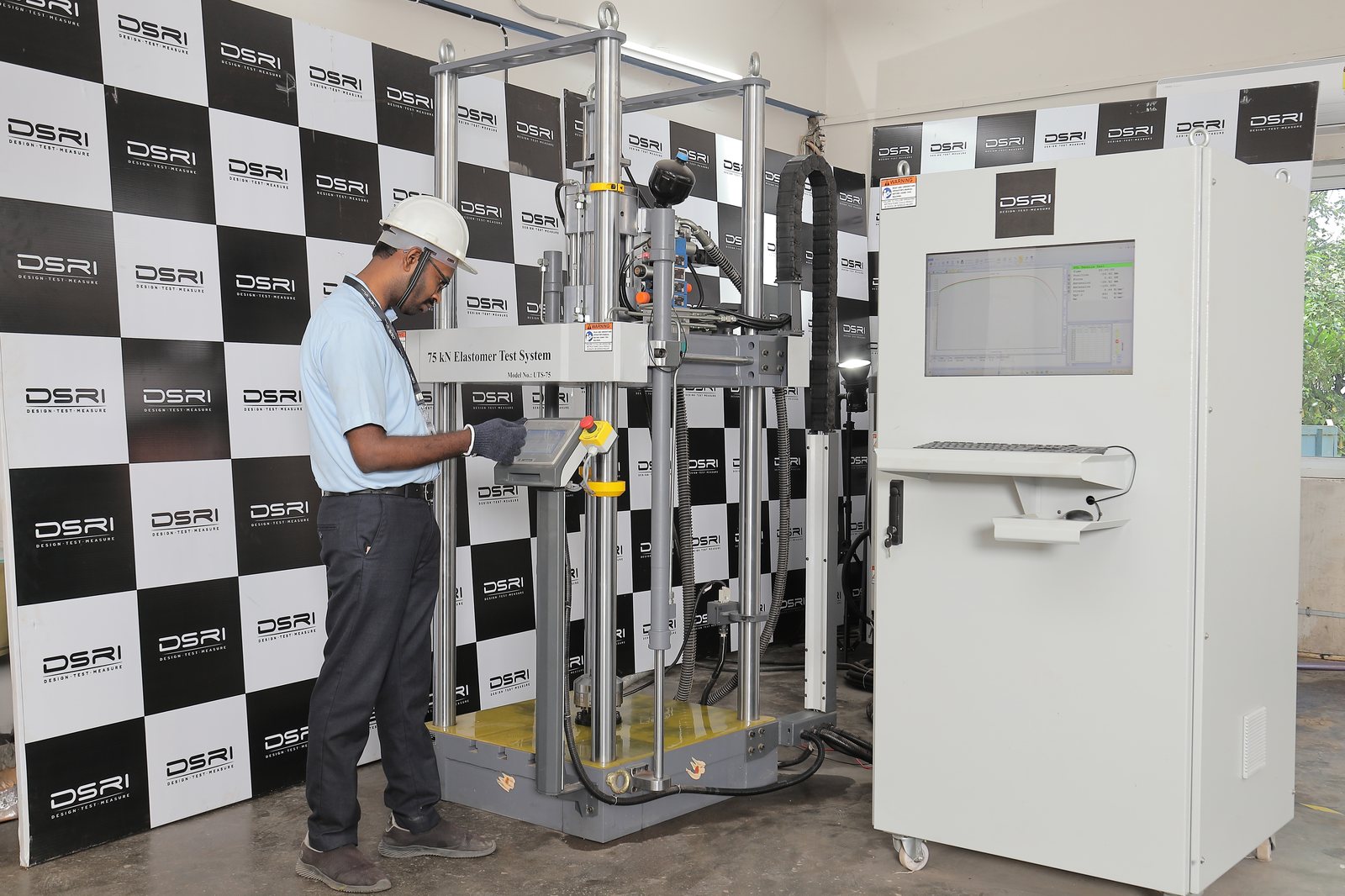
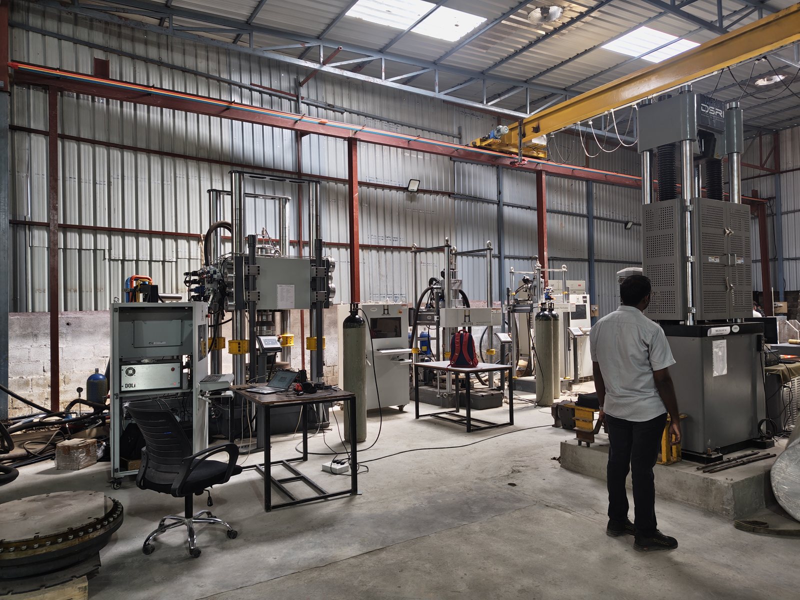
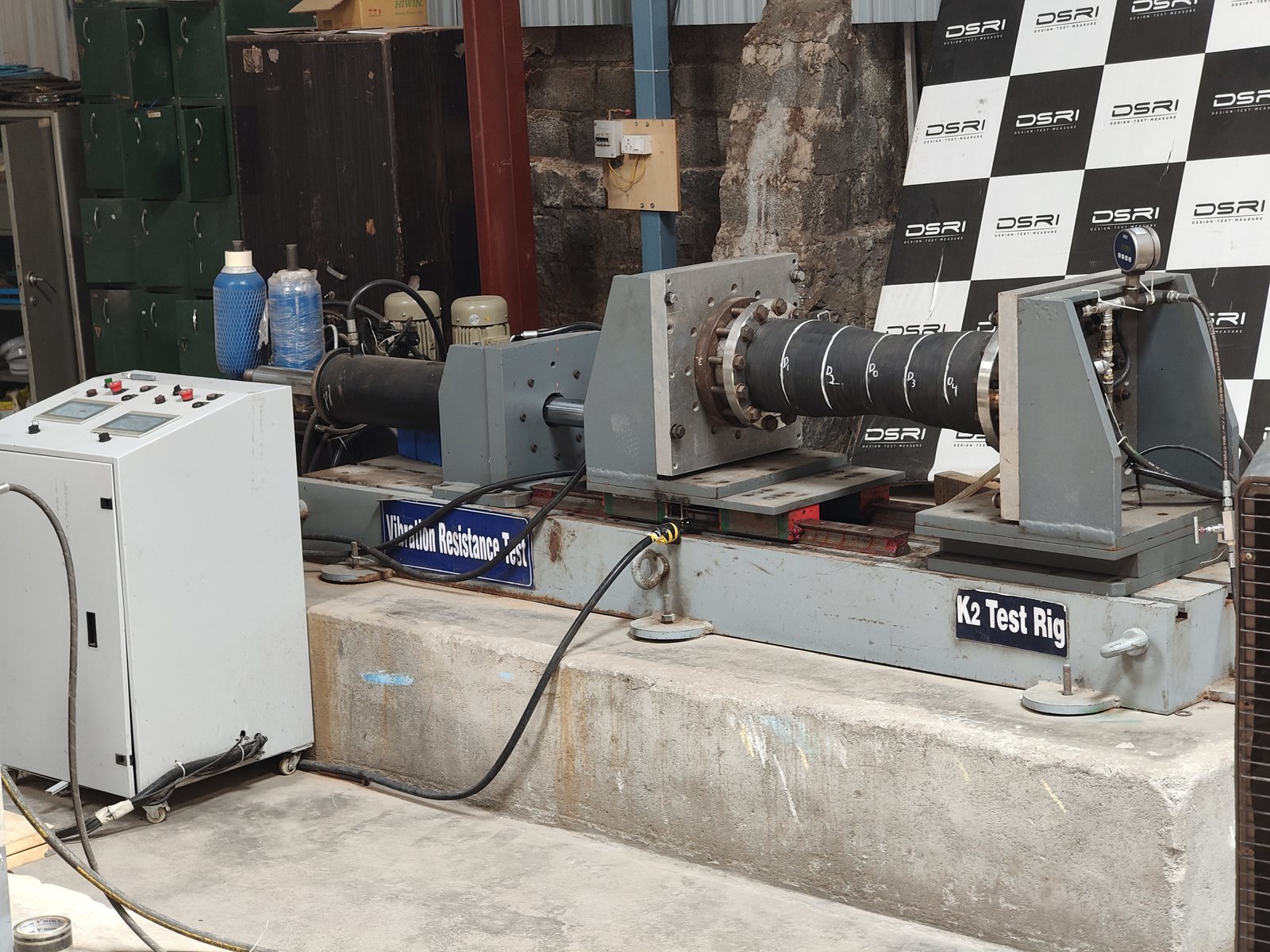
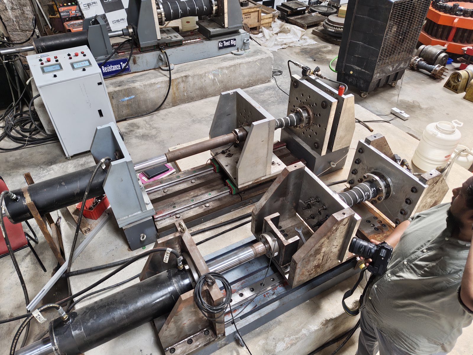
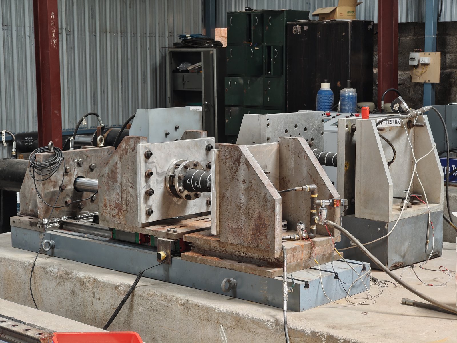
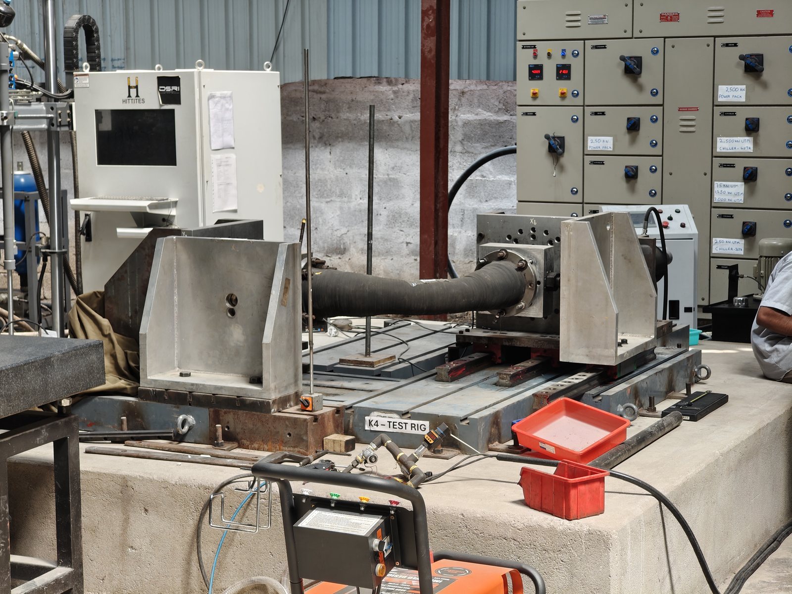
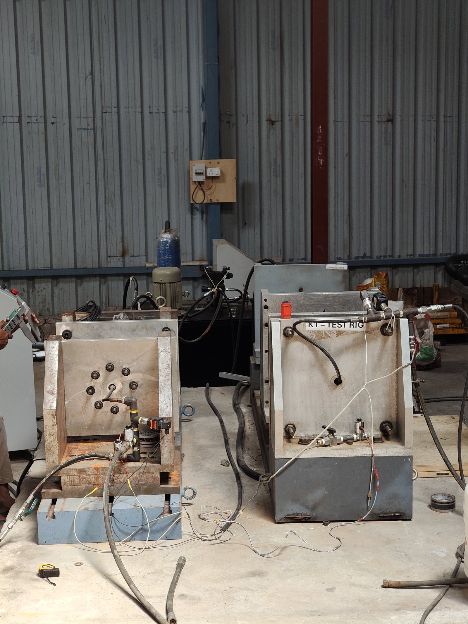
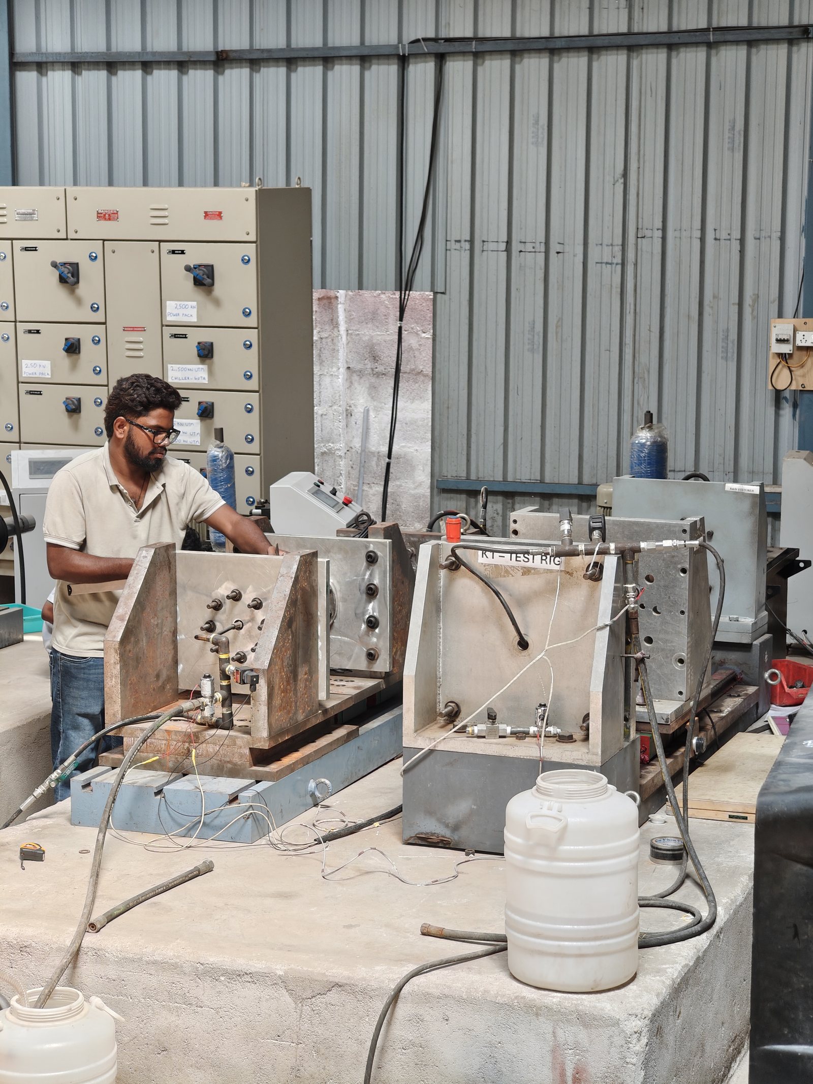
Four accredited groups under one roof, from aerospace alloys to civil-engineering products. Five load frames from 75 kN to 2,500 kN — the 2,500 kN and 250 kN machines are biaxial and dynamic / fatigue rated, a first in the Indian private sector — for tensile, compression, bend, proof-load and fatigue testing to ASTM, ISO, IS and MIL methods.

Metals & aerospace materials
Tensile, yield, elongation, modulus, bend, compression, HCF/LCF fatigue — ASTM E8 / E9 / E466, ISO 6892, IS 1608.
Civil & construction
Rebar couplers and reinforcement: static, slip, cyclic and fatigue — IS 16172, ISO 15835; bend IS 1599.
Fasteners & sub-assemblies
Proof load, tensile, wedge and fatigue of bolts, studs and assemblies — ASTM F606, ISO 3506-1, ISO 7961, ISO 3800.
Rubber & elastomers
Hardness, tear, tensile, compression set, low-temperature flex; MIL-DTL-83528 conductive elastomers — ASTM D2240 / D624 / D412 / D395 / D1329.
Every test below runs on our own machines in Hyderabad and is in the NABL scope of accreditation (TC-12060), reported under the NABL symbol. Variants outside the listed methods — other temperatures, specimen types or customer specifications — are reported as non-accredited. Plain-language version: Mechanical & materials.
Static mechanical properties
metals · weldsTensile testing
A specimen is held in wedge or threaded grips and pulled at a controlled strain or stress rate to fracture while load and extension are logged, giving the full stress–strain curve. Ferrous (steel, stainless, alloy and tool steel, cast iron) and non-ferrous (aluminium, titanium, magnesium, zinc, lead, tungsten) products.
We report- Yield strength / 0.2 % proof stress
- Ultimate tensile strength
- % elongation and reduction in area
- Modulus of elasticity (with extensometer)
Compression testing
Short cylindrical or prismatic specimens are loaded between platens to establish compressive strength and yield behaviour of metals, where the part in service sees compression rather than tension.
We report- Compressive strength
- Compressive yield strength
- Load–deformation curve
Bend testing
Guided or free bend around a mandrel of specified radius to a specified angle, then inspection of the tension face for cracks — a direct check of ductility and soundness for plate, bar and welded joints.
We report- Pass / fail at the specified mandrel and angle
- Location and size of any cracks or openings
Fatigue & cyclic loading
coupons · fasteners · couplersHigh-cycle fatigue (HCF)
Constant-amplitude, load-controlled cycling of machined coupons on the dynamic-rated frames at a set stress ratio and frequency, run to failure or to a specified run-out. Several stress levels build an S–N curve.
We report- Cycles to failure or run-out per specimen
- S–N data at the requested stress ratio
- Fracture location
Fastener fatigue
Axial fatigue of full-size bolts and studs in threaded fixtures, including aerospace bolts qualified against a set number of cycles at a specified load.
We report- Cycles achieved at the specified load
- Failure mode and location (thread, run-out, head fillet)
Cyclic tensile, low- and high-cycle fatigue of couplers
Mechanical splices assembled on the customer's own bar are cycled between specified stress limits — the elastic HCF regime and the large-strain LCF regime that represents seismic loading — then pulled to failure.
We report- Residual slip after cycling
- Cycles survived
- Post-cycling tensile strength
Fasteners & sub-assemblies
bolts · screws · studsFull-size tensile, yield and proof load
Bolts, screws and studs are tested as manufactured rather than as a machined coupon: axial tensile and yield, proof-load hold and wedge tensile to show the head–shank junction is not the weak point.
We report- Ultimate tensile load / strength
- Yield strength
- Proof load: permanent elongation after hold
- Wedge tensile: failure location
Rebar & mechanical splices
civil · metro · bridgesRebar coupler certification
The full static and dynamic sequence a coupler has to pass for acceptance on metro, bridge and high-rise projects, run on the 2,500 kN and 2,000 kN frames for large-diameter bar.
We report- Yield and ultimate tensile strength of the splice
- % elongation (total at maximum force)
- Slip under specified load
- Cyclic, HCF and LCF results as above
Rubber & elastomers
seals · gaskets · mountsTensile, elongation and tear
Dumbbell and tear specimens die-cut from sheet or moulded product, pulled at a fixed crosshead rate.
We report- Tensile strength
- % elongation at break
- Tear strength
Hardness, compression and compression set
Shore-A durometer hardness; compression–deflection; and compression set after a held deflection at temperature — the property that decides whether a seal still seals after years in the joint.
We report- Shore-A hardness
- Compressive force at specified deflection
- % compression set
Low-temperature behaviour
Retraction and flexibility of elastomers conditioned at low temperature, using our climatic chambers for conditioning.
We report- Low-temperature flex / retraction result at the specified temperature
Conductive elastomers (EMI gaskets)
Electrically conductive gasket materials qualified to the military specification: volume resistivity, stability of resistivity after heat ageing and flexing, and life testing.
We report- Volume resistivity
- Electrical stability
- Life test results
| Test | Range · methods (accredited methods: see scope) |
|---|---|
| Tensile: UTS, yield, elongation, reduction in area, modulus | ASTM E8 · ASTM A370 · ISO 6892 · IS 1608 Part 1 · IS 16172 · ASTM F606 · ISO 3506-1 · ISO 7961 · ASTM A1034 |
| Bend test | ASTM A370 · ASTM E190 · ASTM E290 · IS 1599 |
| Compression & compression set | ASTM E9 · ASTM D575 · ASTM D395 |
| Fatigue: HCF / LCF / cyclic tensile | ASTM E466 · ISO 3800 · ISO 7961 · IS 16172 · ISO 15835-2 |
| Rubber & elastomers: hardness, tear, low-temperature flex | ASTM D2240 · ASTM D624 · ASTM D412 · ASTM D1329 |
| Conductive elastomers: volume resistivity, electrical stability, life | MIL-DTL-83528C |
| Slip test (rebar couplers) | IS 16172 |
Equipment
- 2,500 kN biaxial, dynamic / fatigue-rated UTM
- 250 kN biaxial, dynamic / fatigue-rated UTM
- 2,000 kN, 1,250 kN and 75 kN UTMs
- Durometers, extensometers and fixtures
EMI / EMC
Accredited conducted emissions and susceptibility, magnetic-field radiated testing and personnel-borne ESD for military, naval and aerospace equipment — run in our own EMC facility on campus. Electric-field radiated testing (RE102, RS103) runs on our own 8 × 6 × 4.5 m semi-anechoic chamber here; that work sits outside the current NABL scope and is reported without the NABL symbol.
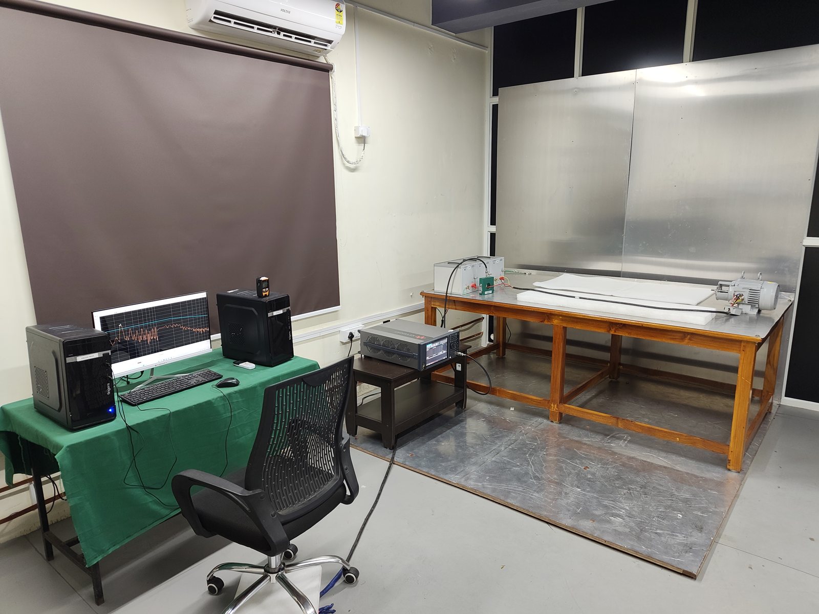
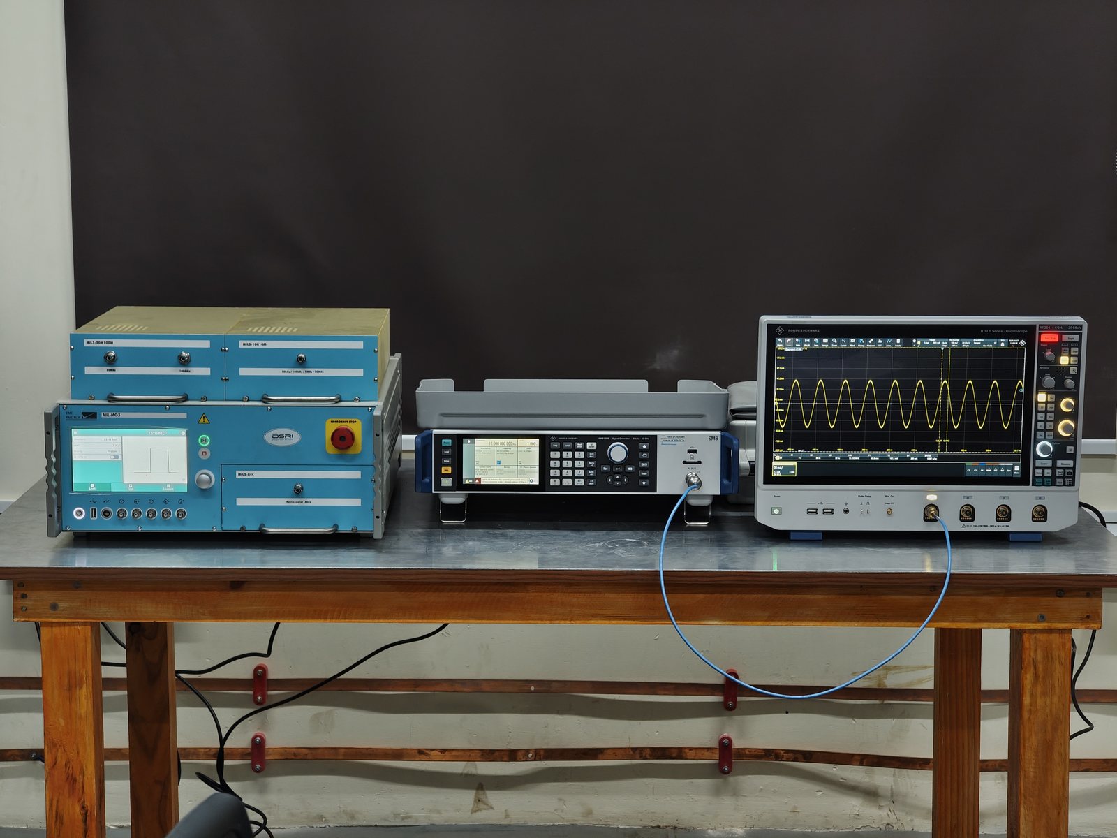
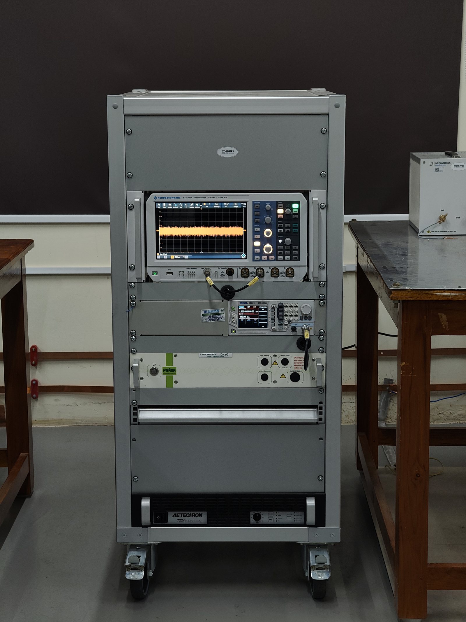
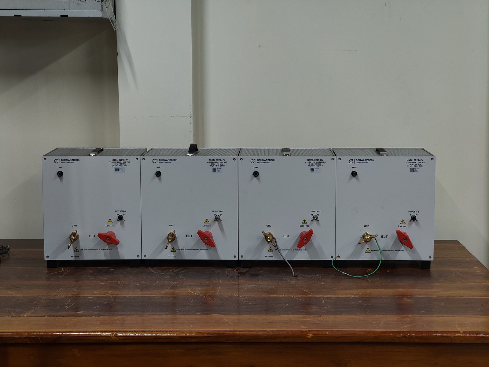
MIL-STD-461 methods tagged NABL are in the scope of accreditation (TC-12060) for revisions E, F and G (CS118: revision G) and are reported under the NABL symbol. Methods tagged non-accredited are run in the same chamber and reported without the NABL symbol. Plain-language version: EMI / EMC.
Emissions (MIL-STD-461)
CE101 · CE102 · RE101 · RE102CE101 / CE102 — conducted emissions
Noise currents and voltages the unit puts onto its power leads: CE101 at low frequency with a current probe, CE102 from 10 kHz to 10 MHz across LISNs, against the limit for your platform.
We report- Emission plots against the applicable limit
- Margin at the worst frequencies
- Operating modes tested
RE101 — radiated emissions, magnetic field
Low-frequency magnetic fields from the unit and its cables, measured with a loop sensor close to every face, against the limit.
We report- Emission plots against the limit
- Worst-case positions
- Operating modes tested
RE102 — radiated emissions, electric field
Electric-field emissions from 10 kHz to 18 GHz at 1 m in the semi-anechoic chamber, with active monopole, biconical and horn antennas and a 26.5 GHz EMI receiver.
We report- Emission plots against the limit, per antenna and polarisation
- Margin at the worst frequencies
- Operating modes tested
Susceptibility (MIL-STD-461)
CS101–CS118 · RS101 · RS103CS101, CS109, CS114, CS115, CS116 — conducted susceptibility
Interference injected onto power leads (CS101), structure (CS109) and cable bundles — continuous RF (CS114), fast impulses (CS115) and damped sinusoidal transients (CS116) — while the unit's performance is monitored.
We report- Levels and frequencies applied
- Unit response against your pass / fail criteria
- Any susceptibility thresholds found
RS101 — radiated susceptibility, magnetic field
Low-frequency magnetic fields applied to each face of the unit with a radiating loop while performance is monitored.
We report- Levels and frequencies applied
- Unit response against your pass / fail criteria
RS103 — radiated susceptibility, electric field
Electric fields from 2 MHz to 18 GHz at 1 m, up to 50 V/m, from a 1,300 W / 250 W / 100 W / 50 W amplifier chain, while performance is monitored.
We report- Field levels and frequencies applied
- Unit response against your pass / fail criteria
- Any susceptibility thresholds found
CS118 — personnel-borne ESD
Contact and air electrostatic discharges to points a person can touch, at the levels of MIL-STD-461G.
We report- Discharge points and levels
- Unit response against your pass / fail criteria
Platform EMC (MIL-STD-464)
system-level requirementsMIL-STD-464 — platform EMC support
Equipment-level testing and measurements that support a platform's system EMC requirements under MIL-STD-464, run in the same chamber and facility as the MIL-STD-461 suite.
We report- Tests, levels and results per the platform specification
| Test | Range · methods (accredited methods: see scope) |
|---|---|
| CE101 / CE102 — conducted emissions | MIL-STD-461 E, F, G |
| CS101, CS109, CS114, CS115, CS116, CS118 — conducted susceptibility | MIL-STD-461 E, F, G |
| RE101 — radiated emissions, magnetic field | MIL-STD-461 E, F, G |
| RE102 — radiated emissions, electric field | MIL-STD-461 E, F, G |
| RS101 — radiated susceptibility, magnetic field | MIL-STD-461 E, F, G |
| RS103 — radiated susceptibility, electric field | MIL-STD-461 E, F, G |
| ESD — personnel-borne | MIL-STD-461G CS118 |
| Platform EMC (equipment-level support) | MIL-STD-464 (non-accredited) |
Equipment
- Semi-anechoic chamber, 8.0 × 6.0 × 4.5 m shield-to-shield, shielding validated 9 kHz – 40 GHz to IEEE-299; 3.0 × 3.0 m pneumatic RF door, 4-tonne floor, 150 mm reflective ground plane
- RE102 at 1 m, 10 kHz – 18 GHz — Keysight 26.5 GHz EMI receiver, active monopole, biconical and horn antennas, single- and three-phase LISNs
- RS103 at 1 m, 2 MHz – 18 GHz, guaranteed 50 V/m — 1,300 W / 250 W / 100 W / 50 W amplifier chain, R&S SMB100B source, PMM EPP603 field probe
- Current probes and injection equipment for the CS114 / CS115 / CS116 suite; NEXIO BAT automation for emissions and susceptibility
Noise, vibration & analysis
Airborne and structure-borne noise surveys with octave-band reporting against naval limits, ISO 3744 sound-power determination, FRF and modal measurement, and design analysis (FEA, CFD) for customers who need an answer, not just a number.
Airborne noise (ISO 3744, MIL-STD-1474E) and structure-borne noise (MIL-STD-740-2) are in the NABL scope of accreditation (TC-12060) and are reported under the NABL symbol. The other measurements below are engineering services, reported without it. Plain-language version: Noise, vibration & analysis.
Airborne noise
sound pressure · sound powerAirborne noise & sound power
Sound pressure measured over a surface around the equipment under specified operating conditions, corrected for background noise and reduced to sound power and octave-band levels.
We report- Sound power level
- Octave-band and dB(A) levels against the limit
- Operating conditions and background correction
Airborne noise to other standards
Sound pressure and sound power to precision, national and maritime methods.
We report- Levels against the specified method and limit
Vibration & structural dynamics
SBN · machinery vibration · FRF · modalStructure-borne noise (SBN)
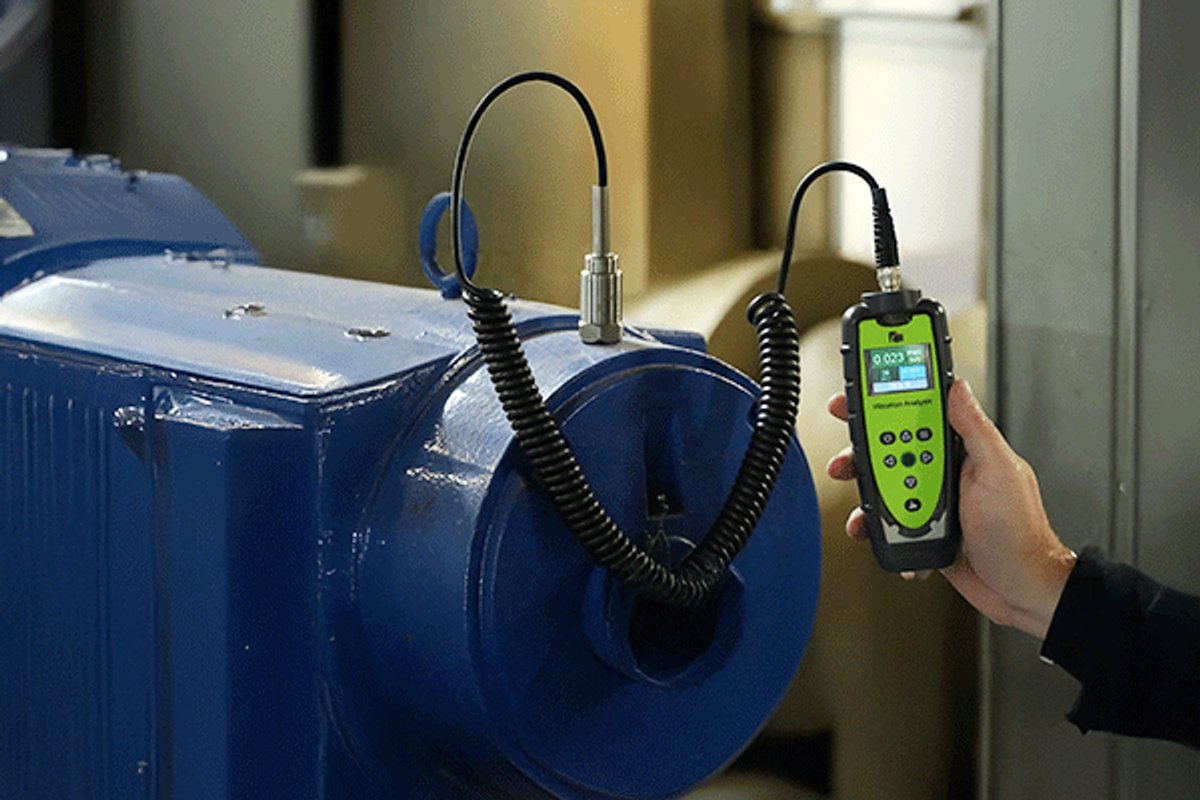
Vibration measured at the mounting feet and on the foundation of running machinery, in octave or narrow bands, against naval structure-borne noise limits.
We report- Vibration levels at each point against the limit
- Operating conditions
- Frequency spectra
Machinery vibration severity
Vibration of running machinery measured on bearings and casings and assessed against severity and naval limits.
We report- Vibration levels against the limits
- Operating conditions
Vibration signature, FRF & order analysis
Multi-channel vibration and noise signatures, frequency response functions, PSD and octave analysis, run-up / coast-down order tracking with tacho.
We report- Spectra, FRFs and order plots
- Interpretation: likely sources and paths
Modal, impedance & mount characterisation
Natural frequencies, mode shapes and damping; point and transfer mobility; dynamic stiffness of resilient mounts under preload.
We report- Mode shapes, frequencies and damping
- Mobility / stiffness spectra
| Test | Range · methods (accredited methods: see scope) |
|---|---|
| Airborne noise (ABN) — accredited | ISO 3744 · MIL-STD-1474E · also ISO 3745 · IS 13161 (Part 3) · IMO Res. A.468 |
| Structure-borne noise (SBN) / vibration measurement — accredited | MIL-STD-740-2 · also NES 1004 · ISO 10816 · DOD-STD-1399 |
| Sound power — accredited | ISO 3744 |
| Vibration signature, FRF, PSD / octave analysis | customer specification (non-accredited) |
| Modal, impedance, mount and fixture characterisation | ISO 7626 · ISO 10846 · ISO 18437 (non-accredited — see Specialisations) |
Equipment
- Multi-channel analysers, accelerometers and microphones
- In-house DSP toolkit for FFT / PSD / octave / FRF reduction
Not sure which test applies?
Send the specification clause or the standard name — our engineers map it to a test plan.